PCE Instruments PCE-FD 20 Bruksanvisning

Les nedenfor 📖 manual på norsk for PCE Instruments PCE-FD 20 (37 sider) i kategorien Måleutstyr. Denne guiden var nyttig for 16 personer og ble vurdert med 4.5 stjerner i gjennomsnitt av 2 brukere

Side 1/37
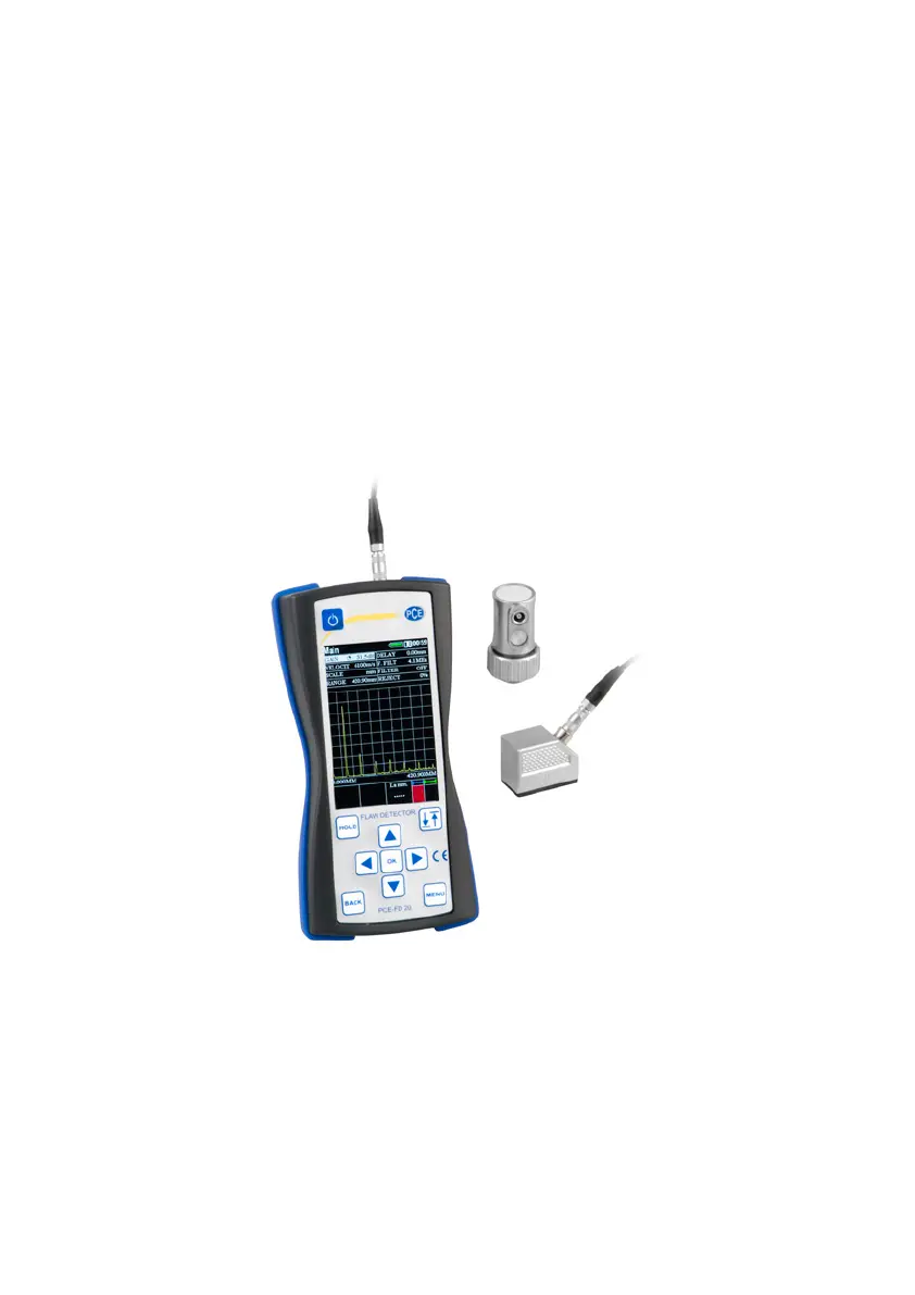
ULTRASONIC FLAW DETECTOR
PCE-FD 20
Operating Manual
2014
PCE Instruments
1
CONTENTS
1. List of Abbreviations used. ………………………………………….2
2. Introduction 2.………………………………………………………….
3. Operating Conditions 3 .……………………………………………….
4. Specications 4.…………………………………………………….….
5. Operating principle 5 .………………………………….…………..….
6. Operation of the device 7 .…………………………………………….
7. 22Basic settings of aw detector ..…………………………………..
8. Device memory . .……………………………………………… ..….29
9. 30Calibration of t .he flaw detector.……………………...………. ….
10. Maintenance.………………………………………………….. 35...
11. . 35 Precautions and trouble shouting.……………………...… …….
12. Contact information ……..……..……..……..……..….………..... . 63
PCE Instruments
2
1. List of Abbreviations used
The manual has the following abbreviations and symbols:
A automatic signaling of defects; FS
TVG time varied gain;
NDT nondestructive testing;
CB calibration block;
US ultrasonic.
2. Introduction
2.1. Appointment of aw detector
Flaw detector is designed for testing of products for the presence of
defects such as discontinuity and homogeneity of materials, semi-
nished products and welds for measuring depth and coordinates of
defects, measure the thickness and sound velocity in the material.
Flaw detector implements shadow, echo and mirror-shadow testing
methods. Flaw detector allows user to create, record and stored in
nonvolatile memory temporary implementation of pulsed ultrasonic
signals to subsequent transmitting to the for analysis andPC
presentation in the form of a document. Integrated liquid crystal
display (LCD) provides a mapping of ultrasonic signals in the form of
A-scan, as well as images of cross sections of testing objects in the
form of B-scans.
Flaw detector can be used in mechanical engineering, aerospace,
metallurgy, mounting hardware, power equipment, as well as for the
testing of transportation facilities.
2.2. Testing
For proper ultrasonic testing user must have testing methods for
similar products and special requirements for ultrasonic testing.
These requirements include: the denition of the task of testing,
selection of suitable control techniques (testing schemes), the
PCE Instruments
3
selection of transducers, an assessment of the known conditions of
control in such materials, the selection of the minimum size of the
reector for this type of product, reject level and so on.
2.3. Velocity of ultrasonic vibrations
Accuracy of measurement of thickness and position of defects
depends on the correct setting of the ultrasonic velocity in the
material. Velocity of ultrasound is dependent on the physical
characteristics of the material and its temperature.
3. Operating Conditions
The device is designed to operate in the following environmental
conditions:
- The temperature from -15 to +50 °C;
- Relative humidity to 95% at a maximum temperature of +35 °C.
The location of the flaw detector must be protected from direct
exposure to dust, moisture and corrosive environments. The eld
strength of radio noise at the location of the aw detector should not
exceed the value of the infringing operation, i.e. creator of the flaw
detector at the amplier input voltage greater than half the maximum
sensitivity. At high eld strength of radio interference must be taken
measures to shielding placements of aw detector from the external
electromagnetic eld.
Operating position of the flaw detector may be any convenient for
the user. To avoid moisture condensation inside the aw detector
when moving it from a cold to a warm place, it is necessary to
sustain aw detector for at least 4 hours before turning in the on
premises.
PCE Instruments
4
4. Specications
Operating Frequency Range
from 1 to 10,0 MHz
The range of measured time intervals
(duration of scanning)
from 6 to 1000 µs
Velocity range
1000 - 9999 m / s
The error of measurement of time
intervals
not exceed ± 0,025 µs
Maximum permissible error of
measurement of the amplitudes of the
signals at the receiver input in the
range from 0 to 110 dB
not exceed ± 0,5 dB;
Testing gain range
125 dB
Averaging over the quantity of starts
from 1 to 16
Digitally recongurable bandpass lter with tunable center
frequency of the lter from 1 Hz to 10 MHz
The range of variation of temporal
sensitivity adjustment (TVG)
40 dB
Number of control points TVG
15
The duration of the excitation pulse to
the load
from 0,0 to 0,5 µs
The amplitude of the excitation pulse to
the 50 Ohm load, not less
100, 200, 300
Operating frequency range of the
receiver on the level -3 dB
from 1 to 10 MHz
Deviation of the amplitudes of input
signals in the range from 10 to 100% of
the screen height not more than
1 dB
Scanning
from 1 to 1000 µs
Delay of scanning
from 0 to 2000 µs
Range of measurement of time
intervals
from 0 to 1000 µs
Setting a delay in the prism of the
from 0 to 15 µs
PCE Instruments
5
probe
Automatic signaling of defects (AFS)
dual-gate
Setting range of AFS gates
from 0 to 2000 µs
Adjusting thresholds of AFS gates
from 0 to 100 %
высоты экрана
Detection of signals
positive half-wave, radio
mode
Dimensions (WxHxD)
80х162х38 mm;
Weight, not more
250 g (without batteries)
Mean time between failures
not less than - 3000
hours
Ultrasound probes used - ultrasonic piezoelectric transducers for
pulse aw detectors.
The dimensions of the operating area of the screen is 48 x 74 mm.;
Electrical power is supplied from the following sources:
-AC power from 100 to 250 V, a frequency of (50 ± 1) MHz;
- AA batteries 1,5 V (3 pcs.).
5 . Operating principle
Operating principle of aw detector is based on the ultrasonic
contact NDT method, which uses the properties of ultrasonic
vibrations to reect from the borders between materials with dierent
acoustic impedance. The ultrasonic transducer emits ultrasonic
impulse into the test object. Reected from the defects or the ed
product surface the echo signals are received by the ultrasonic
transducer. The resulting electrical signals are subject to
amplication, digitization, processing and output to the display.
Displays echoes received by the aw detector is performing as
scanning of type A (A-scan) as well as images of cross sections of
tested objects form of B-scan. in
PCE Instruments
6
5.1. Electronic unit of aw detector
Flaw detector makes the formation of electrical pulses to excite the
piezoelectric transducer, gain derived from the piezoelectric
transducer signals, processing and visualization of the formation and
representation measurements in digital form, saving data in non-
volatile memory and transfer it to PC.
The appearance of the electronic unit is shown o picture 6.1. n
Operation of flaw detector makes by keyboard. Visualization of
signals and display of measurement results, the state of aw
detector and other information is shown on the LCD.
Connecting the probe is carried out by the coaxial cable through the
connectors LEMO, which are located on top side of the devices
body.
The device is powered by a three batteries type AA, or the included
in set external charger connected to the mini-USB connector located
on the bottom of the electronic unit of the aw detector.
5.2. Probes
Flaw detector is designed to operate with the contact, dual element
and separated ultrasonic transducers with an operating frequency in
the range from 1 to 10.0 MHz.
The device uses a generator of bipolar sounding pulses with
adjustable duration, which provides compatibility with both probes:
have integrated terminating inductance and without them, allowing
operation operate with most types of probes on the market.
Depending on the type of probe it is used two types of cables and,
correspondingly, two ways to connect the probe :
- Ultrasonic transducers (type S) are connected via single cable
LEMO-LEMO to the left LEMO connector;
- Dual element transducers (type D) are connected by a double
cable 2LEMO-2LEMO. Right connector is used to connect the
PCE Instruments
7
receiver of the piezoelectric element, the left - transmitter of the
piezoelectric element.
6 . Operation of the device
The basis of flaw detector operation is founded on the ability of
ultrasonic vibrations spread into tested object and reect from
internal defects and object sides. The received signal is amplified
and then converted into digital form processed by the
microprocessor and the graphics and digitally displayed on the
display.
Visualization of signals, display of measurement results, state of the
aw detector and other information are shown on the LCD. Exterior
of the aw detector is shown o picture 6.1. n
Picture 6.1 xterior of he law detector E t f
PCE Instruments
9
the value of the selected parameter) or (increasing the value
of the selected parameter) to set the required value.
To change the discreteness of the selected parameter value
changes, as well as to conrm the selected action use key .
Selected discreteness displays as one of the icons near
the variable parameter.
6.2. Preparing to work with the device
Read this instruction manual and follow its instructions.
Flaw detector must be protected from direct exposure to dust,
moisture, corrosive environments, and must be suciently lit by light
sources.
The field strength of the external interference at the location of the
aw detector must not exceed values that violate its performance. At
high eld strength of external interference must be taken to shielding
placements of the aw detector, as well as its power supply and
connected cables.
When operating from AC power to the flaw detector must be
supplied mains with voltage from 100 to 250 V and with frequency of
(50 ± 1) Hz.
If in the power supply network arise switching noise in power supply
network of the aw detector must enable network lter.
To avoid moisture condensation inside the body, when moving from
a cold environment to a warm, device must be hold in the warmth for
4 hours to dry completely.
At air temperatures below 10°C after switching on flaw detector must
be warmed for at least 15 minutes.
PCE Instruments
10
Controls and indicator of the aw detector located on the front panel,
as shown in Picture 6.1.
Operating connectors are located at the top and bottom sides of the
devices body.
WARNING! To prevent damage of connectors and cables - follow
the instructions below!
Used in the device connectors consist of two parts: the instrument
socket and the cable plug (Pic. 6.2.) .
Picture 6.2. Connector used in the device
A method of connecting and disconnecting the plug and socket
shown on Picture 6.2. When connecting user must ensured that 1.
the points of red color (if any) are plotted on the plug and the socket
are jumped together.
CAUTION: When disconnecting the plug from the socket, hold its
body in the dotted area. Do not pull the cable!!
Picture 6.2.1 Manipulations with LEMO connectors
PCE Instruments
12
The main menu of aw detector is consists of four sections:
- Measurements;
- Archive;
- Setup;
- Information.
6.4. Connecting the transducer to the aw detector
Combined probe is connected to the left connector on the top panel
of aw detector and set in parameter group "Probe" parameter
"DUAL" to "OFF ".
Dual element transducers connect as follows: emitting plate of dual
probe connect to the left connector, and the receiving plate connect
to the right connector on top side of body of the aw detector by
inserting the cable connectors until its click. Set the parameter group
"Probe" parameter "DUAL" to " ". ON
6.5. The main modes of operation of the aw detector
"Measurement" mode - goes to the measurement;
"Archive" mode - displays all stored measurement results and
settings ;
"Settings" mode - in this mode you can set the following settings:
Time, Date, Language, Brightness, Palette, Sound, Auto o, Clear
SD;
"Information" mode - display information about the manufacturer.
To select the required mode, move cursor by keys to select mode,
and conrm selection by pressing the Enter button.
6.5.1 "Measurement" mode
"Measurement" mode is the main mode (Pic. 6.5.1), designed for
ultrasonic testing.
PCE Instruments
13
Picture 6.5.1 "Measurement" mode
All parameters for conguring the measuring part of aw detector
divided into groups, depending on the selected group user gets
access to the various parameters.
Group
Parameters
Main
GAIN
VELOCI
TY
SCALE
RANGE
FILTER
REJECT
Puls/recv
GAIN
RANGE
DELAY
RECTIF
Y
FILTER
REJECT
Gates
GAIN
GATE
START
WIDTH
PARAM.
1
PARAM.
1
Functions
GAIN
DSG
TVG
REJECT
AVG
Probe
DUAL
DELAY
ANGLE
X.VAL
TVG
GAIN
RANGE
DELAY
TVG
POS.
+dВ
DGS
GAIN
DGS
POINT
POS.
mm2
AFS
START
WIDTH
GATE
MEAS.
SEARC
H
ALLARM

Produkspesifikasjoner

Merke: PCE Instruments
Kategori: Måleutstyr
Modell: PCE-FD 20

Trenger du hjelp?

Hvis du trenger hjelp med PCE Instruments PCE-FD 20 still et spørsmål nedenfor, og andre brukere vil svare deg


Måleutstyr PCE Instruments Manualer

Måleutstyr Manualer

Nyeste Måleutstyr Manualer