Ecler AURA-2L150 Bruksanvisning
Les nedenfor 📖 manual på norsk for Ecler AURA-2L150 (34 sider) i kategorien Mottaker. Denne guiden var nyttig for 21 personer og ble vurdert med 4.5 stjerner i gjennomsnitt av 2 brukere
Side 1/34

2
PRECAUTIONS
PACKAGE
CONTENTS
DESCRIPTION &
FEATURES
PANEL
FUNCTIONS
INSTALL &
CONNECT
START-UP &
OPERATION
TECHNICAL
DATA
WARRANTY &
ENVIRONMENT
TABLE OF CONTENTS
1. PRECAUTIONS .......................................................................................................................... 3
1.1 Important Notice ......................................................................................................................... 3
1.2 Key Safety Directions ................................................................................................................ 4
1.3 Cleaning Directions .................................................................................................................... 4
2. WARRANTY & ENVIRONMENT ............................................................................................ 5
3. PACKAGE CONTENTS ............................................................................................................ 5
4. DESCRIPTION & FEATURES .................................................................................................. 6
4.1 Main Features .............................................................................................................................. 6
5. PANEL FUNCTIONS ................................................................................................................. 7
5.1 Front Panel ................................................................................................................................... 7
5.2 Rear Panel .................................................................................................................................... 8
6. INSTALL & CONNECT .............................................................................................................. 9
6.1 Location, Assembly and Ventilation ..................................................................................... 9
6.2 Mains Connection ..................................................................................................................... 10
6.3 Analogue Input Connections ................................................................................................ 11
6.4 Amplified Output Connections ............................................................................................ 12
6.4.1 Out Configurations ................................................................................................................... 12
7. START-UP & OPERATION ................................................................................................... 13
7.1 Start-up ....................................................................................................................................... 13
8. TECHNICAL DATA ................................................................................................................. 14
8.1 Technical Specifications ......................................................................................................... 14
8.1.1 AURA-2L150 ............................................................................................................................. 14
8.1.2 AURA-4L150 ............................................................................................................................. 17
8.1.3 AURA-8L150 ............................................................................................................................. 20
8.1.4 AURA-2H150 ............................................................................................................................ 23
8.1.5 AURA-4H150 ............................................................................................................................ 26
8.2 Mechanical Diagrams .............................................................................................................. 29
8.2.1 AURA-2L150 ............................................................................................................................. 29
8.2.2 AURA-4L150 ............................................................................................................................. 30
8.2.3 AURA-8L150 ............................................................................................................................. 31
8.2.4 AURA-2H150 ............................................................................................................................ 32
8.2.5 AURA-4H150 ............................................................................................................................ 33

3
PRECAUTIONS
PACKAGE
CONTENTS
DESCRIPTION &
FEATURES
PANEL
FUNCTIONS
INSTALL &
CONNECT
START-UP &
OPERATION
TECHNICAL
DATA
WARRANTY &
ENVIRONMENT
1. PRECAUTIONS
1.1 Important Notice
The flashing light with an arrowhead symbol inside an equilateral triangle on it is
intended to alert the user of the presence of non-insulated “dangerous voltage”
within the enclosure, which might be of sufficient magnitude to pose a risk of
electric shock to users.
The exclamation mark within an equilateral triangle is intended to alert the user of
the requirement for important operating and maintenance (servicing), for which
instructions may be found in the literature accompanying the appliance.
WARNING (If applicable): The terminals marked with symbol “ ” may be of sufficient
magnitude to pose a risk of electric shock. The external wiring connected to terminals requires
installation by a technician, or the use of ready-made leads or cords.
WARNING: To prevent fire or shock hazard, do not expose this equipment to rain or humidity.
WARNING: A device with Class I manufacturing ought to be connected to a mains socket
outlet with a protective earthing connection.
WARNING: Ecler products have a long lifetime of more than 10 years. This product
must never be discarded as unsorted urban waste, but must be taken to the nearest
electrical and electronic waste treatment centre.
This equipment has been tested and found to comply with the limits for a Class A
digital device, pursuant to part 15 of the FCC Rules. These limits are designed to provide
reasonable protection against harmful interference when the equipment is operated in a
commercial environment. This equipment generates, uses, and can radiate radio frequency
energy and, if not installed and used in accordance with the instruction manual, may cause
harmful interference to radio communications. Operation of this equipment in a residential area
is likely to cause harmful interference in which case the user will be required to correct the
interference at his own expense.

4
PRECAUTIONS
PACKAGE
CONTENTS
DESCRIPTION &
FEATURES
PANEL
FUNCTIONS
INSTALL &
CONNECT
START-UP &
OPERATION
TECHNICAL
DATA
WARRANTY &
ENVIRONMENT
1.2 Key Safety Directions
1. Read the following directions.
2. Keep the following directions.
3. Heed all warnings.
4. Follow all directions.
5. Do not use this device in proximity to
water.
6. Clean only with a dry cloth.
7. Do not block any ventilation
openings. Install in accordance with
the manufacturer’s instructions.
8. Do not install near any heat sources
such as radiators, heat registers,
stoves, or other devices (including
amplifiers) that may release heat.
9. Do not defeat the safety purpose of
the polarized or grounding type
plug. A polarized plug has two
blades, being one wider than the
other. A grounding type plug has
two blades and a third grounding
prong. The wide blade or the third
prong are provided for your safety. If
the provided plug does not fit into
your outlet, contact a qualified
electrician for a replacement of the
obsolete outlet.
10. Protect the power cord from being
walked on or pinched, particularly at
the plugs, convenience receptacles,
and at the point of exit from the
device.
11. Only use attachments/accessories
specified by the manufacturer.
12. Unplug the device during lightening
sorts or when unused for long periods of
time.
13. Refer all servicing to qualified personnel.
Servicing is required when the device
has been damaged in any way, such as
power supply cord or plug damage,
liquid spillage or objects onto the device,
the device has been exposed to rain or
humidity, does not operate normally, or
has been dropped.
14. Disconnecting from mains: When
switching off the POWER switch, all the
functions and light indicators of the unit
will be stopped, but fully disconnecting
the device from mains is done by
unplugging the power cable from the
mains input socket, therefore, it should
always remain easily accessible
15. Equipment is connected to a socket-
outlet with an earthing connection by
means of a power cord.
16. The marking information is located at the
top/rear of the unit.
17. The device shall not be exposed to
dripping or splashing liquids, and no
liquid-filled objects, such as a filled up
glass, shall be placed on top of the
device.
1.3 Cleaning Directions
Clean the unit with a soft, dry clean cloth or slightly wet with water and neutral liquid
soap only, then dry it with a clean cloth. Be careful that water never gets into the unit through
any hole. Never use alcohol, benzine, solvents or abrasive substances to clean this unit.
NEEC AUDIO BARCELONA, S.L. accepts no liability for any damage that may be caused to
people, animal, or objects due to failure to comply with the warnings above.

5
PRECAUTIONS
PACKAGE
CONTENTS
DESCRIPTION &
FEATURES
PANEL
FUNCTIONS
INSTALL &
CONNECT
START-UP &
OPERATION
TECHNICAL
DATA
WARRANTY &
ENVIRONMENT
2. WARRANTY & ENVIRONMENT
Thank you for choosing Ecler AURA Series!
We greatly value your trust.
It is VERY IMPORTANT to carefully read this manual and to fully understand its
contents before any connecting takes place in order to make the best use of this
equipment, as well as to get the best performance from it.
To ensure optimal operation of this device, we strongly recommend that its
maintenance be carried out by our authorised Technical Services.
All ECLER products are covered by warranty, please refer to www.ecler.com or the
warranty card included with this product for the period of validity and conditions.
Ecler is truly committed with the environment and planet sustainability,
energy saving and CO
2
emission reduction. Recycling materials and using
non-contaminant components are also top priorities in our green crusade.
Ecler has deeply evaluated and analyzed the environmental impacts of all the
processes involved in the production of this product, including packaging, and has
alleviated, reduced and/or compensated for them.
3. PACKAGE CONTENTS
• 1 unit of one of the AURA Series model.
• EU & multiplug mains cords.
• Euroblock Connectors (inputs /outputs)
• Desktop feet, rack 19" installation hardware.
• First Steps Guide.
• Warranty card.

7
PRECAUTIONS
PACKAGE
CONTENTS
DESCRIPTION &
FEATURES
PANEL
FUNCTIONS
INSTALL &
CONNECT
START-UP &
OPERATION
TECHNICAL
DATA
WARRANTY &
ENVIRONMENT
5. PANEL FUNCTIONS
5.1 Front Panel
1. Power Switch: the equipment is switched on by default just switching to ON the front
panel power switch.
2. ON LED: lights up in green colour when the unit is powered ON.
3. Auto Standby indicator LED: lights up in green colour when the Auto Standby function
is enabled.
4. Auto Standby button: enables / disables the Auto Standby function (low power
consumption mode, managed by pairs of channels).
5. Control knobs (1-8 upon model): each front panel LEVEL knob allows to control the
volume of the correspondent amplified audio outputs.
The front panel knobs can be disabled by
means of the VOL Bypass switches -accessible
with a thin screwdriver- from the bottom face of
the chassis.
6. Signal indicator LED (per channel): indicates signal presence in the amplification
output. These indicators light up in green colour when the input signal exceeds -40dBV
threshold.
7. Clip indicator LED (per channel): lights up in red colour when the input signal exceeds
-0,9dBV.
8. Protect /Thermal. indicator LED (per channel): lights up in red colour when the general
protection circuit of the channel is activated, or in orange colour when the temperature
limiter is in operation, with fast blinking when temperature reaches 83 °C (181.4 °F) or
steady when the temperature reaches 125 °C (257 °F) and in this case the equipment
goes into protection mode.

8
PRECAUTIONS
PACKAGE
CONTENTS
DESCRIPTION &
FEATURES
PANEL
FUNCTIONS
INSTALL &
CONNECT
START-UP &
OPERATION
TECHNICAL
DATA
WARRANTY &
ENVIRONMENT
9. Standby indicator LED (per pair of channels): lights up in orange colour when a couple
of adjacent channels enter into Standby (low power consumption) mode.
Auto Standby threshold can be selected, for every 2 adjacent channels, by means
of an internal jumper, between -40db / -50 dB values.
10. Link indicator LED (per channel): lights up in white colour when the link function is
activated = the channel gets its input audio signal from IN1 in the rear panel (same signal
that CH1 gets), instead of getting it from INX, where X is the channel count index.up
when the maximum power is reached.
5.2 Rear Panel
1. Mains socket base
2. Amplified outputs, OUT 1-2, or 1-4, or 1-8 (upon model), 2-pin Euroblock or 3 pin
Euroblock (Low Impedance or High Impedance, respectively, upon models)
3. Link button for INX to IN1 (X=2 to 8, upon models).
4. Analogue inputs, IN1-2, or 1-4, or 1-8 (upon model), 3-pin Euroblock, balanced.

9
PRECAUTIONS
PACKAGE
CONTENTS
DESCRIPTION &
FEATURES
PANEL
FUNCTIONS
INSTALL &
CONNECT
START-UP &
OPERATION
TECHNICAL
DATA
WARRANTY &
ENVIRONMENT
6. INSTALL & CONNECT
The equipment must be correctly grounded (ground resistance, Rg = 30 Ohm or less). The
environment must be dry and dustless. Do not expose the unit to rain or water splashes, and
do not place liquid containers or incandescent objects like candles on top of the unit.
Do not obstruct the ventilation grilles with any kind of material. If the device requires any
intervention and/or connection/disconnection, it must be first powered off.
Do not handle the speaker output terminals with your device turned on, there are high
voltages. The output cabling should be connected by a qualified technician. Otherwise only use
pre-made flexible cables. There are no user serviceable parts inside the amplifier.
Non-compliance with the instructions or neglecting warnings may cause malfunction
or even damage the unit.
• Avoid turning on the device without the speakers connected to its outputs and without
having previously set the volume/gain controls to minimum level.
• Always use shielded cables to make connections between devices.
• In an amplifier, avoid placing the speaker output cables close to other signal cables
(micro, line…). This may cause the system to oscillate, damaging the amplifier and speakers.
6.1 Location, Assembly and Ventilation
AURA series devices have a 19" rack format (1RU).
It is very important not to enclose the amplifier or expose it to extreme temperatures as it
generates heat.
It is also necessary to encourage the airflow through the ventilation holes of the chassis.
If multiple products are installed in the same rack or in a cabinet with closed doors, it
is highly recommended to install fans in their upper and lower ends for a forced airflow from
the bottom up. This upward air flow will help to dissipate the heat generated inside.
Please ensure that there is always, at least, one free rack unit between an AURA
amplifier and other equipment installed above and below it in the rack cabinet. This is
essential for the fanless convection ventilation to work properly and thus ensure correct
operation of the amplifier throughout its lifetime.
Regular maintenance of dust removal is highly recommended as dust can impede
airflow and hinder heat dissipation.

10
PRECAUTIONS
PACKAGE
CONTENTS
DESCRIPTION &
FEATURES
PANEL
FUNCTIONS
INSTALL &
CONNECT
START-UP &
OPERATION
TECHNICAL
DATA
WARRANTY &
ENVIRONMENT
6.2 Mains Connection
AURA operates on alternating voltages from 100-240 V @ 50-60Hz (±10%). This device is
equipped with an oversized power supply capable of adapting without any type of adjustment
to the mains voltage of any country in the world.
On the front panel, there is an on/off switch for the unit.
ON Led on the frontal panel lights up when unit is switched on.
To enable/disable the Auto Standby mode (per pairs of channels) just push the Auto
Standby button on the front panel. The Auto Standby LED will light in green accordingly.
Do not allow the mains cable to run parallel to the shielded cables carrying the audio
signal, as this may cause humming.

11
PRECAUTIONS
PACKAGE
CONTENTS
DESCRIPTION &
FEATURES
PANEL
FUNCTIONS
INSTALL &
CONNECT
START-UP &
OPERATION
TECHNICAL
DATA
WARRANTY &
ENVIRONMENT
6.3 Analogue Input Connections
AURA rear panel provides analogue, balanced, line level signal inputs. The selection of
hardware inputs and it’s routing to the unit’s amplified channels are performed from its physical
connections and LINK button.
Signal input connectors are 3 position screw terminal block. The wiring is:
For unbalanced connection short-circuit pin to pin − as reported on the picture.
Live or direct signal
>
Pin
+
Cold or inverted signal
>
Pin
-
Ground
>
Pin

12
PRECAUTIONS
PACKAGE
CONTENTS
DESCRIPTION &
FEATURES
PANEL
FUNCTIONS
INSTALL &
CONNECT
START-UP &
OPERATION
TECHNICAL
DATA
WARRANTY &
ENVIRONMENT
6.4 Amplified Output Connections
The rear panel is fitted with two position screw terminal block for each amplified output (low
impedance models) or with three position screw terminal block for each amplified output
(high impedance models, 70/100V outputs).
Always respect the relative polarity for outputs (+ and - on each output connector),
wiring and speakers.
6.4.1 Out Configurations
Select the appropriate operation mode to do not damage the loudspeakers. Never connect
loads below 4 ohms when working in low impedance mode.
Make sure to match the impedance of the total load connected to the loudspeakers,
when working in low impedance for a correct performance.
The connection cable that joins the amplifiers outputs and the loudspeakers must be
of good quality, sufficient section and as short as possible. This is most important when the
distances to cover are long ones i.e., up to 10 meters it is recommended to use a section not
inferior to 2.5mm
2
and for superior distances 4mm
2
.

14
PRECAUTIONS
PACKAGE
CONTENTS
DESCRIPTION &
FEATURES
PANEL
FUNCTIONS
INSTALL &
CONNECT
START-UP &
OPERATION
TECHNICAL
DATA
WARRANTY &
ENVIRONMENT
8. TECHNICAL DATA
8.1 Technical Specifications
8.1.1 AURA-2L150
AURA-2L150
INPUTS
Number of Inputs
2
Analogue input connection type
3-pin Euroblock, balanced, pitch 3,5 mm
Input configuration
Input link to CH1 selector per input
AMPLIFIED OUTPUTS
Number of amplified outputs
2
Amplified output connection type
2-pin Euroblock. Pitch: 5 mm
OUTPUT POWER All channels driven @ 1%THD
Max output power @ 8Ω
Max output power @ 4Ω
75W
150W
SIGNAL
Voltage gain
27,8 dB
Input sensitivity
0 dBV
2,21 dBu
1 Vrms
Input impedance
>500kΩ (balanced)
Max input level
+12dBV
14,21 dBu
Frequency response
15Hz-30kHz (-3dB, 1W @ 4Ω)
THD + Noise
< 0,01 % (from 1W to full power output @ 4Ω)
SNR
100 dBA (from 20Hz - 20kHz)
Crosstalk
>80dB (@ 1kHz)
CMRR
> 55 Typ (from 20Hz-20kHz)
Damping factor
>150 (DF @ 8 Ω, 20 Hz - 400 Hz)
ELECTRICAL
Power supply
Universal, regulated SMPS with PFC
AC mains requirement
100-240 V @ 50-60Hz (±10%)
Power factor correction
> 0,92 (Output Power > 1/4 Max Output Power)
AC mains connector
IEC C14 inlet (10Amax, Power cord 10Amax)
POWER & HEAT @230VAC
1/4 POWER, @ 4Ω (all channels driven)
Power
103,8 W | 112,9 VA
Current Draw
0,492 Arms
Thermal Loss
24,95 kcal/h | 99 BTU/h
1/8 POWER, @ 4Ω (all channels driven)
Power
58,97 W | 67,4 VA
Current Draw
0,293 Arms
Thermal Loss
18,55 kcal/h | 73,62 BTU/h

15
PRECAUTIONS
PACKAGE
CONTENTS
DESCRIPTION &
FEATURES
PANEL
FUNCTIONS
INSTALL &
CONNECT
START-UP &
OPERATION
TECHNICAL
DATA
WARRANTY &
ENVIRONMENT
IDLE (all channels driven)
Power
11,6 W | 24,4 VA
Current Draw
0,106 Arms
Thermal Loss
9,98 kcal/h | 35,59 BTU/h
SLEEP MODE (all channels driven)
Power
8,9 W | 21,97 VA
Current Draw
0,096 Arms
Thermal Loss
7,65 kcal/h | 30,38 BTU/h
POWER & HEAT @120VAC
1/4 POWER, @ 4Ω (all channels driven)
Power
106,7 W | 108 VA
Current Draw
0,988 Arms
Thermal Loss
27,66 kcal/h | 109,76 BTU/h
1/8 POWER, @ 4Ω (all channels driven)
Power
60,11 W | 61,95 VA
Current Draw
0,536 Arms
Thermal Loss
19,44 kcal/h | 77,17 BTU/h
IDLE (all channels driven)
Power
11,7 W | 13,66 VA
Current Draw
0,119 Arms
Thermal Loss
10,06 kcal/h | 39,93 BTU/h
SLEEP MODE (all channels driven)
Power
9,1 W | 11,36 VA
Current Draw
0,099 Arms
Thermal Loss
7,83 kcal/h | 31,06 BTU/h
TECHNOLOGIES
Amplification technology
Class D
Energy saving
Auto Standby function selectable (Auto Standby by pairs of
channels)
Efficiency
72% (1/4 POWER, @ 4Ω, 230VAC)
Cooling
Convection (fanless)
PROTECTIONS
DC protection
Yes
HF protection
Yes
Short-circuit protection
Yes
Clip limiter
Yes
Thermal protection
Yes
LOCAL CONTROL
Attenuators
Front panel knobs per channel
VOL (default)/BYPASS option) (VOL/BYPASS selectable by a switch
at the bottom)
RUN/SLEEP mode
Auto Standby function
Front panel button
(Auto Standby ON/OFF button per unit. -50dB (default) or -40dB,
internally selectable. Auto Standby time: 60 seconds)

16
PRECAUTIONS
PACKAGE
CONTENTS
DESCRIPTION &
FEATURES
PANEL
FUNCTIONS
INSTALL &
CONNECT
START-UP &
OPERATION
TECHNICAL
DATA
WARRANTY &
ENVIRONMENT
Power ON/OFF
Front panel switch (green LED indicator)
MONITORING
Signal Present
SIGNAL LED (Green) per channel (trigger @- 40 dBV)
Clipping
CLIP LED (Red) per channel
Protect
PROT LED (Red) by pairs of channels (Combined PROT/TH LED)
Standby
AUTO STANDBY ON/OFF LED (Green) per unit
Standby / Mute
AUTO STANDBY (Orange) by pairs of channels
Thermal
TH LED (Orange) by pairs of channels (combined PROT/TH LED)
On
ON LED (Green) per unit
Link
LINK LED (White) per channel
PHYSICAL
Operating temperature
-10º to 50º C
14º to 122º F
Operating humidity
5 - 85% RH, non-condensing
Storage temperature
-10º to 50º C
14º to 122º F
Storage humidity
5 - 85% RH, non-condensing
Dimensions (WxHxD)
482.6x44x275 mm. / 19x1.73x10.83 inches
Weight
3.0 kg / 6.6 lb
Shipping dimensions (WxHxD)
590x75x400mm. / 23.23x2.95x15.75 inches
Shipping weight
4.55 kg / 10.03lb
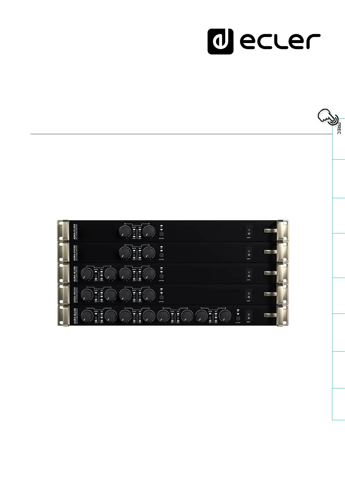
Produkspesifikasjoner
Merke: | Ecler |
Kategori: | Mottaker |
Modell: | AURA-2L150 |
Trenger du hjelp?
Hvis du trenger hjelp med Ecler AURA-2L150 still et spørsmål nedenfor, og andre brukere vil svare deg
Mottaker Ecler Manualer
12 August 2025
12 August 2025
12 August 2025
27 Februar 2025
27 Februar 2025
27 Februar 2025
27 Februar 2025
11 Februar 2025
11 Februar 2025
11 Februar 2025
Mottaker Manualer
- Mottaker Bosch
- Mottaker Power Dynamics
- Mottaker Vonyx
- Mottaker Akg
- Mottaker Jensen
- Mottaker Hartke
- Mottaker Philips
- Mottaker Goobay
- Mottaker Avantree
- Mottaker Godox
- Mottaker Cayin
- Mottaker Meridian
- Mottaker Teufel
- Mottaker Fender
- Mottaker Axton
- Mottaker Kogan
- Mottaker DJI
- Mottaker McIntosh
- Mottaker Behringer
- Mottaker Sony
- Mottaker Pro-Ject
- Mottaker Yamaha
- Mottaker Morel
- Mottaker Extron
- Mottaker Lindy
- Mottaker Pioneer
- Mottaker NuPrime
- Mottaker AudioControl
- Mottaker Audac
- Mottaker Rotel
- Mottaker Audio-Technica
- Mottaker Toa
- Mottaker Marantz
- Mottaker Rega
- Mottaker Vox
- Mottaker Pyle
- Mottaker Shure
- Mottaker Roland
- Mottaker NAD
- Mottaker Wet Sounds
- Mottaker JVC
- Mottaker VMV
- Mottaker S.M.S.L
- Mottaker Kicker
- Mottaker Auna
- Mottaker OSD Audio
- Mottaker DataVideo
- Mottaker Audizio
- Mottaker Bluesound
- Mottaker Blackstar
- Mottaker Hertz
- Mottaker Kenwood
- Mottaker Cambridge
- Mottaker MB Quart
- Mottaker Aplic
- Mottaker CSL
- Mottaker NUVO
- Mottaker IFi Audio
- Mottaker Henry Engineering
- Mottaker Block
- Mottaker Smart-AVI
- Mottaker Advance
- Mottaker Artsound
- Mottaker Denon
- Mottaker Marshall
- Mottaker Yorkville
- Mottaker Valcom
- Mottaker Mosconi
- Mottaker JBL
- Mottaker Infinity
- Mottaker Helix
- Mottaker Soundstream
- Mottaker Klipsch
- Mottaker PAC
- Mottaker Bellari
- Mottaker Rolls
- Mottaker Ground Zero
- Mottaker Karma
- Mottaker Glemm
- Mottaker EA
- Mottaker Match
- Mottaker Renkforce
- Mottaker Scansonic
- Mottaker SPL
- Mottaker Audiotec Fischer
- Mottaker Crunch
- Mottaker QSC
- Mottaker A-NeuVideo
- Mottaker Atlona
- Mottaker Classé
- Mottaker FoneStar
- Mottaker Monitor Audio
- Mottaker Peavey
- Mottaker Crown
- Mottaker Fosi Audio
- Mottaker Graupner
- Mottaker Antelope Audio
- Mottaker Vaddio
- Mottaker Stinger
- Mottaker ESX
- Mottaker Omnitronic
- Mottaker Rocstor
- Mottaker Russound
- Mottaker MEE Audio
- Mottaker Monacor
- Mottaker GigaBlue
- Mottaker Mx Onda
- Mottaker Black Hydra
- Mottaker Electro-Voice
- Mottaker Boss
- Mottaker JL Audio
- Mottaker Shanling
- Mottaker Atlas Sound
- Mottaker Comica
- Mottaker Ashly
- Mottaker MuxLab
- Mottaker Audiolab
- Mottaker Lectrosonics
- Mottaker Memphis Audio
- Mottaker Alpine
- Mottaker Evolution
- Mottaker AVM
- Mottaker Primare
- Mottaker Elektrobock
- Mottaker PureLink
- Mottaker Kramer
- Mottaker ATen
- Mottaker Blustream
- Mottaker Mtx Audio
- Mottaker Yaesu
- Mottaker Musical Fidelity
- Mottaker RCF
- Mottaker Vimar
- Mottaker Bogen
- Mottaker RDL
- Mottaker Harman Kardon
- Mottaker Dynacord
- Mottaker Ferguson
- Mottaker DAP Audio
- Mottaker REL Acoustics
- Mottaker Inovonics
- Mottaker KanexPro
- Mottaker BZBGear
- Mottaker Bresser
- Mottaker InLine
- Mottaker Ram Audio
- Mottaker Gefen
- Mottaker Phoenix Gold
- Mottaker Strong
- Mottaker Vincent
- Mottaker HiFi ROSE
- Mottaker Intelix
- Mottaker Comprehensive
- Mottaker Deaf Bonce
- Mottaker Fiio
- Mottaker Lab Gruppen
- Mottaker GlobalSat
- Mottaker AVMATRIX
- Mottaker Kathrein
- Mottaker Imperial
- Mottaker Hifonics
- Mottaker Hotone
- Mottaker Phonic
- Mottaker AudioSource
- Mottaker Taga Harmony
- Mottaker SoundTube
- Mottaker James
- Mottaker Geemarc
- Mottaker Devialet
- Mottaker ButtKicker
- Mottaker Antelope
- Mottaker Futaba
- Mottaker Neumann
- Mottaker Crest Audio
- Mottaker Mooer
- Mottaker Rexing
- Mottaker Marshall Electronics
- Mottaker Atoll
- Mottaker August
- Mottaker Inter-M
- Mottaker Esoteric
- Mottaker Alto
- Mottaker Konig & Meyer
- Mottaker Lumantek
- Mottaker Aguilar
- Mottaker Mark Levinson
- Mottaker Selfsat
- Mottaker Proel
- Mottaker Audibax
- Mottaker Line 6
- Mottaker Luxman
- Mottaker Sound Ordnance
- Mottaker Wavtech
- Mottaker Dual
- Mottaker Parasound
- Mottaker Benchmark
- Mottaker Koda
- Mottaker Technical Pro
- Mottaker Naim
- Mottaker Anthem
- Mottaker Audison
- Mottaker Loxjie
- Mottaker Clare Controls
- Mottaker Edwards Signaling
- Mottaker Iriver
- Mottaker Hegel
- Mottaker PTN-electronics
- Mottaker Datapath
- Mottaker Sunfire
- Mottaker DLS
- Mottaker Triax
- Mottaker Xtrend
- Mottaker Nubert
- Mottaker VigilLink
- Mottaker Harper
- Mottaker SmartSystem
- Mottaker DARTS
- Mottaker ETON
- Mottaker Elipson
- Mottaker Streacom
- Mottaker Phonocar
- Mottaker Diamond Audio
- Mottaker Rockville
- Mottaker CYP
- Mottaker DS18
- Mottaker Coastal Source
- Mottaker Swissonic
Nyeste Mottaker Manualer
15 August 2025
14 August 2025
14 August 2025
13 August 2025
13 August 2025
13 August 2025
12 August 2025
12 August 2025
12 August 2025
12 August 2025