Toa VP-2241 INCL Bruksanvisning

Toa Mottaker VP-2241 INCL

Les nedenfor 📖 manual på norsk for Toa VP-2241 INCL (194 sider) i kategorien Mottaker. Denne guiden var nyttig for 3 personer og ble vurdert med 4.6 stjerner i gjennomsnitt av 2 brukere

Side 1/194
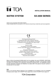
INSTALLATION MANUAL
MATRIX SYSTEM SX-2000 SERIES
When an EN 54-16 compliant SX-2000 system has to be installed, then read "APPENDIX: ADDITIONAL
INSTALLATION INSTRUCTIONS FOR AN EN 54-16 COMPLIANT SYSTEM" in this document carefully
and follow up the installation and configuration requirements explained herein. This APPENDIX contains
the basic description of settings and installations, so please refer to the general instruction sections in this
document for more details.
Note
Refer to the Instruction Manual attached to the VX-2000DS/3000DS for the installation of the the VX-
2000DS or VX-3000DS Emergency power supply, the VX-2000PF Power supply frame, and the VX-200PS
Power supply unit.
1134
TOA Electronics Europe GmbH
Suederstrasse 282, 20537 Hamburg, Germany
1134-CPR-102
EN 54-16: 2008
Fire detection and fire alarm systems
— Part 16: Voice alarm control and indicating equipment
Options:
Emergency microphone(s)
Manual reset of the voice alarm condition
Indication of faults related to voice alarm zones
Phased evacuation
Voice alarm condition output to CIE
Redundant power amplifiers
14
DoP 14-003
Thank you for purchasing TOA's Matrix System.
Please carefully follow the instructions in this manual to ensure long, trouble-free use of your equipment.
2
TABLE OF CONTENTS
1. NOMENCLATURE AND FUNCTIONS
................................................. 6
1.1. SX-2000SM System Manager ............................................................................... 6
1.2. SX-2000AI Audio Input Unit ................................................................................ 10
1.3. SX-2100AI Audio Input Unit ................................................................................. 15
1.4. SX-2000AO Audio Output Unit ............................................................................ 20
1.5. SX-2100AO Audio Output Unit ............................................................................ 26
1.6. SX-2000CI Control Input Unit .............................................................................. 32
1.7. SX-2000CO Control Output Unit ......................................................................... 34
1.8. RM-200SF Fireman's Microphone ...................................................................... 36
1.9. RM-200SA Remote Microphone ......................................................................... 39
1.10. RM-210 Remote Microphone Extension ............................................................ 42
1.11. RM-200RJ Terminal Unit .................................................................................... 43
1.12. Optional Modules ............................................................................................... 44
1.12.1. SX-2 0 0RM Remote Microphone Interface Module .................................. 44
1.12.2. D-921E Microphone/Line Input Module ................................................... 45
1.12.3. D-921F Microphone/Line Input Module ................................................... 45
1.12.4. D-922E Microphone/Line Input Module ................................................... 46
1.12.5. D-922F Microphone/Line Input Module ................................................... 46
1.12.6. D-936R Stereo Input Module ................................................................... 47
1.13. VP-2064, VP-2122, VP-2241, and VP-2421 Power Amplifiers ........................... 48
1.14. VP-200VX Power Amplifier Input Module .......................................................... 48
1.15. VP-3154, VP-3304, and VP-3504 Power Amplifiers .......................................... 49
2. INSTALLATION ................................................................................................ 51
2.1. SX-2000SM ......................................................................................................... 51
2.1.1. System reset enable/disable settings (DIP switch 3 operation) ................. 51
2.1.2. Failure reset operation method settings (DIP switch 4 operation) ............ 52
2.2. SX-2000AI and SX-2100AI .................................................................................. 53
2.2.1. Module installation .................................................................................... 53
2.2.2. Setting the device number ........................................................................ 54
2.2.3. Changing the type of control outputs (SX-2100AI only) ............................ 55
2.3. SX-2000AO and SX-2100AO .............................................................................. 57
2.3.1. Setting the device number ........................................................................ 57
2.3.2. 24 V Emergency cutoff input settings (DIP switch 8 operation)
(SX-2000AO only) ...................................................................................... 58
2.3.3. Converting an output into a transformer-balanced output
(SX-2000AO only) ...................................................................................... 59
2.3.4. Changing the method of power supply for the control input signal
applied to the Local Audio Control Input Terminal (SX-2100AO only) ...... 62
2.4. SX-2000CO ......................................................................................................... 64
2.5. RM-200SF, RM-200SA, and RM-210 ................................................................. 66
2.5.1. RM-200SF and RM-200SA device number settings
(DIP switches 1 – 3 operation) ................................................................... 66
2.5.2. Adjusting microphone sensitivity (RM-200SF: DIP switch 5 operation
or RM-200SA: DIP switch 4 operation) ..................................................... 68
2.5.3. CPU OFF function (general urgency all-call) settings
(RM-200SF: DIP switch 6 operation or RM-200SA: DIP switch 5 operation)
...... 70
2.5.4. RM Communication function setting
(RM-200SF: DIP switch 4 operation or RM-200SA: DIP switch 6 operation)
..... 71
2.5.5. Using an external microphone (RM-200SA only) ..................................... 72
2.5.6. Compressor function setting ..................................................................... 74
2.5.7. Microphone fault detection function setting (RM-200SA only) .................. 76

Produkspesifikasjoner

Merke: Toa
Kategori: Mottaker
Modell: VP-2241 INCL
Innebygd skjerm: Nei
Vekt: 8100 g
Bredde: 482 mm
Dybde: 340.5 mm
Høyde: 88.4 mm
Tilkoblingsteknologi: Koblet med ledninger (ikke trådløs)
Antall kanaler: 1 kanaler
Produktfarge: Sort
Driftstemperatur (T-T): 0 - 40 °C
Signal-til-støy-forhold (SNR): 80 dB
Total Harmonic Distortion (THD): 1
Lyd-utgang kanaler: 1.0 kanaler
DC inngående spenning: 20 - 40 V
Frekvensrekkevidde: 40 - 16000 Hz
Tilkoblingstype høyttalere: Binding post
Peak effekt per kanal: 240 W

Trenger du hjelp?

Hvis du trenger hjelp med Toa VP-2241 INCL still et spørsmål nedenfor, og andre brukere vil svare deg