Tripp Lite SmartOnline SU5000RT4UHV Bruksanvisning
Tripp Lite
uforstyrret strømtilførsel (UPS)
SmartOnline SU5000RT4UHV
Les nedenfor 📖 manual på norsk for Tripp Lite SmartOnline SU5000RT4UHV (116 sider) i kategorien uforstyrret strømtilførsel (UPS). Denne guiden var nyttig for 13 personer og ble vurdert med 4.6 stjerner i gjennomsnitt av 7 brukere
Side 1/116

1
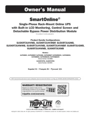
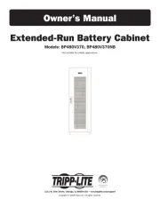
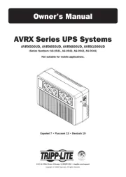
Owner’s Manual
1111 W. 35th Street, Chicago, IL 60609 USA • www.tripplite.com/support
Copyright © 2013 Tripp Lite. All rights reserved. SmartOnline is a trademark of Tripp Lite.
SmartOnline™
Single-Phase 5kVA–6kVA
Intelligent True On-Line UPS Systems
• Includes UPS system with internal battery system (5&6kVA),
detachable PDU and detachable parallel PDU modules (6kVA)
Not suitable for mobile applications.
Important Safety Warnings 2
Mounting 3
Connection 9
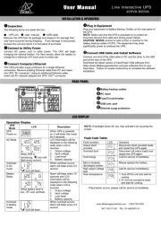
Features 4
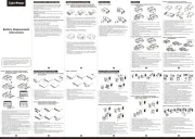
Internal Battery Replacement 28
Español 30
Storage and Service 29
Français 59
Warranty and Warranty Registration 29
Ðóññêèé 88
Optional Connection 12
Manual Bypass Operation 14
Operation 15
Warranty
Registration:
register online today for a
chance to win a FREE Tripp Lite
product—www.tripplite.com/warranty
Produkspesifikasjoner
| Merke: | Tripp Lite |
| Kategori: | uforstyrret strømtilførsel (UPS) |
| Modell: | SmartOnline SU5000RT4UHV |
Trenger du hjelp?
Hvis du trenger hjelp med Tripp Lite SmartOnline SU5000RT4UHV still et spørsmål nedenfor, og andre brukere vil svare deg
uforstyrret strømtilførsel (UPS) Tripp Lite Manualer
18 August 2025
18 August 2025
18 August 2025
18 August 2025
18 August 2025
18 August 2025
18 August 2025
18 August 2025
18 August 2025
18 August 2025
uforstyrret strømtilførsel (UPS) Manualer
Nyeste uforstyrret strømtilførsel (UPS) Manualer
16 Oktober 2025
16 Oktober 2025
6 Oktober 2025
5 Oktober 2025
5 Oktober 2025
2 Oktober 2025
1 Oktober 2025

1 Oktober 2025

1 Oktober 2025
1 Oktober 2025