Tripp Lite SmartPro Digital Bruksanvisning
Tripp Lite
uforstyrret strømtilførsel (UPS)
SmartPro Digital
Les nedenfor 📖 manual på norsk for Tripp Lite SmartPro Digital (4 sider) i kategorien uforstyrret strømtilførsel (UPS). Denne guiden var nyttig for 7 personer og ble vurdert med 4.9 stjerner i gjennomsnitt av 4 brukere
Side 1/4

Owner’s Manual
SMX1500LCD Digital UPS System
Not suitable for mobile applications.
Español Français
3
6
Important Safety Instructions
SAVE THESE INSTRUCTIONS
The manual contains instructions and warnings that should be followed during the installation, operation and storage of this product. Failure to heed these
warnings will void your warranty.
UPS Location Warnings
• TheUPSisdesignedforindooruseonlyinacontrolledenvironment,
away from excess moisture, temperature extremes, conductive
contaminants, dust or direct sunlight.
• LeaveadequatespacearoundallsidesoftheUPSforproperventilation.
• Donotmountunitwithitsfrontorrearpanelfacingdown(atany
angle).Mountinginthismannerwillseriouslyinhibittheunit's
internalcooling,eventuallycausingproductdamagenotcovered
underwarranty.
UPS Connection Warnings
• ConnecttheUPSdirectlytoaproperlygroundedACpoweroutlet.Donot
plugtheUPSintoitself;thiswilldamagetheUPS.
• DonotmodifytheplugoftheUPS,anddonotuseanadapterthat
eliminatesthegroundconnectionoftheUPS.
• DonotuseextensioncordstoconnecttheUPStoanACoutlet.The
warrantywillbevoidifanythingotherthanTrippLitesurgesuppressors
areusedtoconnecttheUPStoanoutlet.
• IftheUPSreceivespowerfromamotor-drivenACgenerator,the
generatormustprovideclean,filtered,computer-gradeoutput.
Equipment Connection Warnings
• Useofthisequipmentinlifesupportapplicationswherefailureofthis
equipmentcanreasonablybeexpectedtocausethefailureofthelife
supportequipmentortosignificantlyaffectitssafetyoreffectivenessisnot
recommended.Donotusethisequipmentinthepresenceofaflammable
anesthetic mixture with air, oxygen or nitrous oxide.
• Donotconnectsurgesuppressorsorextensioncordstotheoutputofthe
UPS.ThismightdamagetheUPSandwillvoidthesurgesuppressorand
UPSwarranties.
Battery Warnings
• TheUPSdoesnotrequireroutinemaintenance.DonotopentheUPSfor
anyreason.Therearenouser-serviceablepartsinside.
• Batteriescanpresentariskofelectricalshockandburnsfromhighshort-
circuitcurrent.Observeproperprecautions.Donotdisposeofthebatteries
inafire.DonotopentheUPSorbatteries.Donotshortorbridgethe
batteryterminalswithanyobject.UnplugandturnofftheUPSbefore
performingbatteryreplacement.Usetoolswithinsulatedhandles.Battery
replacement should be performed only by authorized service personnel
usingthesamenumberandtypeofbatteries(sealedLead-Acid).The
batteriesarerecyclable.Refertoyourlocalcodesfordisposalrequirements.
TrippLiteoffersacompletelineofreplacementbatteriesatwww.tripplite.com.
• DonotattempttoaddexternalbatteriestotheUPS.
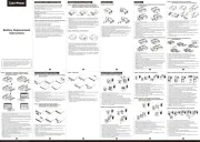
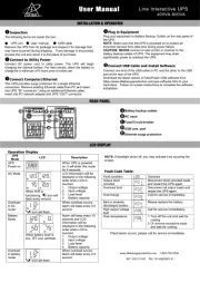
Quick Installation
STEP 1: Place the UPS in a horizontal or vertical (tower) position. To
installtheUPSina4-postrack,attachtheincludedhardwaretotheUPSas
shown in diagram
A
.ToinstalltheUPSina2-postrack,attachtheincluded
hardware tothe UPS as shown in diagram
B
. Then, using an assistant if
necessary, lifttheUPS andattachit toa standardrackwith user-supplied
hardware. Caution:IftheUPSisinstalledinarack,allowatleast2cm
(0.75in.)clearanceaboveandbelowtheunit.IftheUPSisplacedflat
onasurface,doNOTstackanyotherobjectdirectlyontopoftheunit.
The UPS will stand in a tower position without the aid of the included
hardware.Forincreasedstability,however,TrippLiterecommendsattaching
the included hardware as shown in diagram
C
.Ineitherposition,theuser
must determine the fitness of hardware and procedures before installation.
TheUPSandincludedhardwarearedesignedforcommonracktypesand
maynotbeappropriateforallapplications.TheLCDdisplaymayberotated
tomatchtheorientationoftheUPS.Carefullyinsertasmalltoolintheslots
atthesideoftheLCDtoremoveitfromtheUPShousing,thenrotatethe
LCDandpressitbackintoplace.
CAUTION:TobalancetheUPSsafelywhenplacedinaverticalposition,
makesuretheLCDDisplayislocatedatthetopofthefrontpanel.
STEP2:Connectauser-suppliedpowercord*totheUPS,thenplugthe
UPSintoawalloutlet.**
AfterpluggingtheUPSintoawalloutlet,pushtheON/OFFbuttonfor
onesecondtoturntheUPSon(see section).Basic Operation
PleaseNote! willnotTheUPS turn on automatically in the presence of
live utility power.
*The UPS system does not include an input power cord. The user-supplied power cord should have
an IEC-320-C13 connector (commonly found on detachable power cords for desktop computers) at
one end in order to connect to the AC input of the UPS.
**Use an outlet that doesn't share a circuit with a heavy electrical load such as an air conditioner or
refrigerator.
STEP3:PlugyourequipmentintotheUPS.
Insertthefemaleconnectorsofthedetachablepowercordsthatcamewith
the UPS system into theACinputs of the attached equipment. Insert the
maleconnectorsintoanyoftheUPSsystem'savailableoutlets.
The UPS is designed to support electronic equipment only. Connected
equipmentwilloverloadtheUPSifthetotalVAratingsforalltheequipment
connected to the outlets exceeds the UPS Output Capacity. To find VA
ratings,look atequipmentnameplates. Iftheequipment islistedin amps,
multiply thenumber ofamps by 230volts todetermineVA.(Example: 1
amp×230 volts=230VA).Ifunsurewhether theoutletsareoverloaded,
runaself-test(see“MUTE/TEST”Buttondescription).
STEP 4: Optional Installation. The UPS includes USB and RS-232
communication ports as well as Tel/DSL/Ethernet and Coaxial surge
protection jacks. These connections are optional; the UPS will work
properly without these connections.
NotcompatiblewithPoE(PoweroverEthernet)applications.
A
C
B
CAUTION:TheUPSmustbepluggedintoaliveACoutletandturnedon
for24hoursafterinitial installationtofullychargetheinternalbattery.
Connectedequipment willreceiveutility-suppliedACpower (ifpresent)
immediately after the UPS is plugged in and turned on, but connected
equipmentwillnotreceivefullbatterybackupintheeventofablackout
orseverebrownoutunlesstheinternalbatteryisfullycharged.
1
9
200810036.indd 1 11/4/2008 2:22:40 PM

2
Basic Operation (Front Panel)
• Press and hold the ON/OFF Button for one
second.* If utility power is absent, pressing the Button will “cold-
start”theUPS,i.e.turnitonandsupplypowerfrombattery.**
• Press and hold the ON/OFF Button for one
second.*TheUPSwillbeturnedoffcompletely.
* The alarm will beep once after one second has passed. ** Providing runtime proportionate to the
UPS battery's level of charge.
• Briefly press and release
the MUTE/TEST button. Note: continuous alarms that warn
toshutdownconnectedequipmentimmediatelycannotbesilenced.
• with the UPS plugged in and turned on,
pressandholdtheMUTE/TESTbuttonfortwoseconds.Continueholding
the button until the alarm beeps several times and the UPS performs a
self-test.See“ResultsofaSelf-Test”below.Note:connected equipment
mayremainconnectedduringaself-test.
The testwilllastapproximately10 secondsasthe
UPSswitchestobatterytotestloadcapacityandcharge.AllLCDDisplay
iconswillbeilluminatedandtheUPSalarmwillsound.
•If the “FAULT” icon remains lit and the alarm continues to
soundafterthetest,thebattery-supportedoutletsareoverloaded.To
cleartheoverload,unplugsomeequipmentfromthebatterysupported
outletsandruntheself-testrepeatedlyuntilthe“FAULT”iconisno
longer lit and the alarm is no longer sounding.
•If the “REPLACE” icon remains lit and the alarm continues to
sound after the test, the UPS batteries need to be recharged
or replaced. Allow the UPS to recharge continuously for 24
hours, and repeat the self-test. If the icon continues to
illuminate after repeated self tests, contact Tripp Lite for service.
Batteryreplacementshouldonlybeperformedbyqualifiedservice
personnel.IftheUPSrequiresbatteryreplacement,TrippLiteoffersa
complete line of replacement batteries at www.tripplite.com.
The LCD Display indicates a varietyof UPS operational conditions.All
descriptionsapplywhen theUPSispluggedintoanACoutlet andturned
on.TheLCD displaymayberotatedtomatchtheorientationofthe UPS.
CarefullyinsertasmalltoolintheslotsatthesideoftheLCDtoremoveit
fromtheUPShousing,thenrotatetheLCDandpressitbackintoplace.
This meter measures, in real time, the
AC voltage that the UPS system receives from the utility wall outlet.
Althoughthemeter mayoccasionallydisplayinputvoltageswhichstray
(duetopoorqualityutilityservice)outsidetherangeofstandardcomputer
tolerance,rest assured that the UPSis designed to continuously supply
connectedequipmentwithstable,computer-gradeoutputthroughtheuse
ofautomaticvoltageregulation. In theeventofa blackout(power loss),
severebrownout(low power)orovervoltage(highpower), theUPSwill
relyontheinternalbatterytosupplycomputer-gradeoutputvoltage.
This meter displays the
approximate charge level (in 20% increments) of the internal battery.
During a blackout or severe brownout, the UPS will switch to battery
power, the“ONBAT”iconwillbeilluminatedandthechargelevelwill
deplete.
This icon will
illuminate whenever the UPS is automatically correcting low AC line
voltage without depleting battery power. This is a normal, automatic
operationoftheUPS,andnoactionisrequired.
This icon will
illuminateand analarm will sound after a self-testto indicate the UPS
battery needs to be recharged or replaced.Allow the UPS to recharge
continuouslyfor24hours,andrepeattheself-test.Iftheiconcontinuesto
illuminate,contactTrippLiteforservice.Batteryreplacementshouldonly
beperformedby qualifiedservicepersonnel.IftheUPSrequiresbattery
replacement,TrippLiteoffersacompletelineofreplacementbatteriesat
www.tripplite.com.
During a severe brownout or
blackout, this icon illuminates and an alarm sounds (4 short beeps
followedby apause) to indicate the UPS is operating from its internal
batteries. Monitor the “Battery Capacity” Meter to determine the
approximatebatterychargelevelavailabletosupportequipment.Duringa
prolongedbrownoutor blackout,thealarmwillsoundcontinuously(and
the“BATTERYCAPACITY”Meterwillshowone20%capacitysegment
shaded)toindicatethebatteriesarenearlyoutofpower;savefilesandshut
downyourequipmentimmediately.
This icon will illuminate and an alarm will sound
afteraself-testtoindicatethebattery-supportedoutletsareoverloaded.To
clear the overload, unplug some of the equipment from the battery-
supportedoutletsandruntheself-testrepeatedlyuntiltheiconisnolonger
illuminated and the alarm is no longer sounding.
AdjuststhebrightnessoftheLCDDisplay
Storage
Toavoidbatterydrain,allconnectedequipmentshouldbeturnedoffanddisconnectedfromtheUPS.
PressandholdtheON/OFFbuttonforonesecond.YourUPSwillbecompletelyturnedoff(deactivated),
andwillbereadyforstorage.IfyouplanonstoringyourUPSforanextendedperiod,fullyrechargethe
UPSbatterieseverythreemonths.PlugtheUPSintoaliveACoutlet,turnitonbypressingandholding
theON/OFFbuttonforonesecond,andallowthebatteriestorechargefor24hours.Ifyouleaveyour
UPSbatteriesdischargedforalongperiodoftime,theywillsufferapermanentlossofcapacity.
Note on Labeling
Two symbols are used on the label.
V~ : AC Voltage
V : DC Voltage

Battery Backup/Surge Protected Outlets: These IEC-320-C13 outlets
provide both battery backup and surge protection. Plug your computer,
monitorandothercriticalequipmentintotheseoutlets.NOTE:DONOT
PLUGLASERPRINTERSINTOTHESEOUTLETS.
USB Communication Port: This port can connect your UPS to any
computer for automatic file saves and unattended shutdown in the event
ofapowerfailure.UsewithTrippLite'sPowerAlertSoftware(available
asaFREEdownloadatwww.tripplite.com)andappropriateUSBorDB9
cable. A USB or DB9 cable may be included with your UPS. If the
appropriatecabledidnotcome withyour UPS,anyuser-suppliedDB9
pass-through or USB cable may then be used to connectyour UPS to
your computer.
Note: This connection is optional. The UPS will work properly without this
connection. This UPS System provides basic communication compatibility Note:
with most integrated Windows
®
, Macintosh
®
and Linux
®
power management
applications.
ContactClosureCommunication(viaRS-232Port):TheRS-232port
has a contact closure communication feature that can be used to
communicate withconnected equipment thatdoes not support USBor
RS-232communications.WhentheUPSisinNormalmode,pins1and
9 are bridged. When the UPS is in Backup mode, pins 1 and 8 are
bridged.
Tel/DSL/EthernetProtectionJacks:RJ-45jacksprovidesurgeprotectionfor
asingletelephone,fax,modem,DSLorEthernetline.Connectatelephonecord
orEthernetcablefromthewalljackororiginaldatasourcejackdirectlytothe
Tel/DSL/Ethernetjacklabeled“IN.”ConnectatelephonecordorEthernetcable
fromtheTel/DSL/Ethernetjacklabeled“OUT”directlytotheequipmenttobe
protected.TheUPSsystemmustbethefirstitemconnectedtothewalljackor
originaldatasourcejack.TheUPSsystemmustbepluggedintoagroundedAC
outletinordertoprovidesurgeprotectiontoconnectedequipment.Connecting
yourequipmenttothesejacksisoptional.YourUPSwillworkproperlywithout
this connection. Not compatible with PoE (Power over Ethernet) applications.
ACInput:ThisIEC-320-C14connectoracceptsauser-suppliedpowercord
withaplugappropriateforthelocalsite'sutilityoutlets.
CoaxialProtectionJacks:Gold-platedjacksprovidesurgeprotectionfora
singlecoaxialline.Connectacoaxialcablefromthewalljackdirectlytothe
coaxialjacklabeled“IN.”Connect acoaxial cablefromthecoaxial jack
labeled“OUT”directlytotheequipmenttobeprotected.TheUPSsystem
mustalwaysbethefirstitemconnectedtothewalljack.TheUPSsystem
must be plugged into a grounded AC outlet in order to provide surge
protectiontoconnectedequipment.Makesurecoaxialcablesconnectedto
satellitedishes,antennas,etc.arealsogrounded.Connectingyourequipment
to these jacks is optional. The UPS will work properly without this
connection.
PowerSensitivityDial:Thedefaultsettingforthedialisfullcounterclockwise
rotation.ThedefaultallowstheUPStoprotectagainstwaveformdistortions
in theAC input power by switching tobatterypowerfor as long as the
problem is detected. At sites supplied by substandard utility power or
generatorpower,chronicwaveformdistortion(orfrequentbrownouts)could
causetheUPStoswitchtobatterytoooften,drainingbatteryreserves.Itmay
be possible to optimize the level of protection for a particular site by
experimentingwithsensitivitysettings.Asthedialisturnedclockwise,the
UPSbecomesmoretolerantofwaveformvariations.WARNING:Equipment
may malfunction when exposed to distorted AC waveforms. When
experimenting withsensitivitysettings,operateconnected equipment in a
safe “test mode” in order to evaluate results without disrupting critical
operations. Continue thetest untilall expected lineconditionshave been
encountered.
CircuitBreaker:If thecurrentdrawnbytheequipment connectedtothe
UPSexceedstheMaximumLoadRatingforlongerthanafewseconds,the
circuit breaker will activate and interruptAC power to prevent possible
damage. When the circuit breaker activates, its plunger will pop up.
Disconnect excess equipment and allow the breaker to cool one minute
beforedepressingtheplungertoresetthebreaker.
Basic Operation (Rear Panel)
Tel/DSL/Ethernet
ProtectionJacks
USBPort ACInputBatteryBackup/Surge
ProtectedOutlets
Before returning your UPS for service, follow these steps: 1. Review the installation and operation instructions in this manual to ensure that the service problem does not originate from a misreading
of the instructions. 2. If the problem continues, do not contact or return the UPS to the dealer. Instead, call Tripp Lite at (773) 869-1234 domestically or (773) 869-1212 internationally. A service
technician will ask for the UPS model number, serial number and purchase date and will attempt to correct the problem over the phone. 3. If the problem requires service, the technician will issue you
a Returned Material Authorization (RMA) number, which is required for service. If you require packaging, the technician can arrange to send you proper packaging. Securely pack the UPS to avoid
damage during shipping. Do not use Styrofoam beads for packaging. Any damages (direct, indirect, special, incidental or consequential) to the UPS incurred during shipment to Tripp Lite or an
authorized Tripp Lite service center is not covered under warranty. UPS Systems shipped to Tripp Lite or an authorized Tripp Lite service center must have transportation charges prepaid. Mark the
RMA number on the outside of the package. If the UPS System is within the 2-year warranty period, enclose a copy of your sales receipt. Return the UPS for service using an insured carrier to the
address given to you by the Tripp Lite service technician.
WEEE Compliance Information for Tripp Lite Customers and Recyclers (European Union)
Under the Waste Electrical and Electronic Equipment (WEEE) Directive and implementing regulations, when customers buy new electrical and electronic equipment from Tripp Lite they are entitled to:
• Send old equipment for recycling on a one-for-one, like-for-like basis (this varies depending on the country)
• Send the new equipment back for recycling when this ultimately becomes waste
Regulatory Compliance Identification Numbers
For the purpose of regulatory compliance certifications and identification, your Tripp Lite product has been assigned a unique series number. The series number can be found on the product
nameplate label, along with all required approval markings and information. When requesting compliance information for this product, always refer to the series number. The series number should
not be confused with the marking name or model number of the product.
Tripp Lite follows a policy of continuous improvement. Product specifications are subject to change without notice.
Made in China.
9
10
8
7
4
5
6
4
5
6 7
Coaxial
ProtectionJacks
8
PowerSensitivity
Dial
9
11
CircuitBreaker
10 11
Service
RS-232SerialPort
(DB9)
Produkspesifikasjoner
Merke: | Tripp Lite |
Kategori: | uforstyrret strømtilførsel (UPS) |
Modell: | SmartPro Digital |
Vekt: | 13340 g |
Bredde: | 438.2 mm |
Dybde: | 266.7 mm |
Høyde: | 88.9 mm |
LED-indikatorer: | Ja |
Opprinnelsesland: | China |
Pakkevekt: | 15670 g |
Antall USB 2.0-porter: | 1 |
Sertifisering: | CE, GOST, SASO, FCC Part 15 Category A, FCC Part 68 |
Utgangseffekt: | 900 W |
Utgangsspenning (maks.): | 240 V |
UPS topologi: | Linje-Interactive |
Bølgeform: | Sinus |
Batteriladetid: | 4.5 timer |
Inngangsspenning (maks.): | 230 V |
Produktfarge: | Sort |
Pakkedybde: | 553 mm |
Pakkehøyde: | 198.1 mm |
Pakkebredde: | 388.1 mm |
Driftstemperatur (T-T): | 0 - 40 °C |
Oppbevaringstemperaturomåde (Celsius): | -15 - 50 °C |
Bærekraftsertifikater: | RoHS |
Formfaktor: | Rackmontering/tårn |
Inngangsfrekvens: | 50/60 Hz |
Overspenningsvern: | Ja |
Rack-kapasitet: | 2U |
Kommunikasjonsserieporter: | 1 |
Relativ luftfuktighet under drift (H-H): | 0 - 95 |
Oppdateringsresponstid: | 4 ms |
Antall AC outlets: | 8 AC-utganger |
Masterkassens (ytterkassens) GTIN (EAN/UPC): | 10037332126075 |
Masterkassens (ytterkassens) bruttovekt: | 15670 g |
Masterkassens (ytterkassens) lengde: | 553 mm |
Produkter per masterkasse (ytterkasse): | 1 stykker |
Masterkassens (ytterkassens) bredde: | 388.1 mm |
Masterkassens (ytterkassens) høyde: | 198.1 mm |
Hørbare alarmer: | Ja |
Strøm (maks.): | 5.5 A |
AC-utgangstyper: | C13 kopling |
Strømuttak: | C14 kopling |
Strømstøt energivurdering: | 890 J |
Output strømkapasitet (VA): | 1.5 kVA |
Inngangsspenning (min.): | 230 V |
Utgangsspenning (min.): | 220 V |
Normal backuptid ved halv belastning: | 12 min |
Normal backuptid ved full belastning: | 4.5 min |
Trenger du hjelp?
Hvis du trenger hjelp med Tripp Lite SmartPro Digital still et spørsmål nedenfor, og andre brukere vil svare deg
uforstyrret strømtilførsel (UPS) Tripp Lite Manualer
18 August 2025
18 August 2025
18 August 2025
18 August 2025
18 August 2025
18 August 2025
18 August 2025
18 August 2025
18 August 2025
18 August 2025
uforstyrret strømtilførsel (UPS) Manualer
- Apc
- NGS
- Salicru
- Furman
- Green Cell
- Ditek
- Sven
- CyberPower
- LC-Power
- Be Quiet!
- Minuteman
- Gys
- ATen
- Qoltec
- Jung
Nyeste uforstyrret strømtilførsel (UPS) Manualer
2 Oktober 2025
1 Oktober 2025
1 Oktober 2025
1 Oktober 2025
1 Oktober 2025
1 Oktober 2025
1 Oktober 2025
30 September 2025
30 September 2025
29 September 2025