Viking DEV900 Bruksanvisning
Viking
eksoshette
DEV900
Les nedenfor 📖 manual på norsk for Viking DEV900 (12 sider) i kategorien eksoshette. Denne guiden var nyttig for 16 personer og ble vurdert med 4.8 stjerner i gjennomsnitt av 8.5 brukere
Side 1/12
1
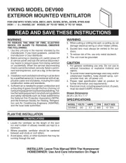
WARNING
TO REDUCE THE RISK OF FIRE, ELECTRIC
SHOCK, OR INJURY TO PERSONS, OBSERVE
THE FOLLOWING:
1. Use this unit only in the manner intended by the
manufacturer. If you have questions, contact the
manufacturer or your distributor.
2. Before servicing or cleaning unit, switch power off
at service panel and lock the service disconnect-
ing means to prevent power from being switched
on accidentally. When the service disconnecting
means cannot be locked, securely fasten a promi-
nent warning device, such as a tag, to the service
panel.
3. Installation work and electrical wiring must be done
by a qualified person(s) in accordance with all ap-
plicable codes and standards, including fire-rated
construction codes and standards.
4. Sufficient air is needed for proper combustion and
exhausting of gases through the flue (chimney) of
fuel burning equipment to prevent backdrafting. Fol-
low the heating equipment manufacturer's guideline
and safety standards such as those published by
the National Fire Protection Association (NFPA),
and the American Society for Heating, Refrigera-
tion and Air Conditioning Engineers (ASHRAE),
and the local code authorities.
WARNING
CAUTION
1. For general ventilating use only. Do not use to
exhaust hazardous or explosive material and
vapors.
2. To avoid motor bearing damage and noisy and/or
unbalanced impellers, keep drywall spray, con-
struction dust, etc. off power unit.
3. Please read specification label on product for
further information and requirements.
4. Electrical circuit, including speed control, (if used),
must be rated 6 AMPS minimum.
Blower Dimensions
28.25 x 24.75 x 7.17
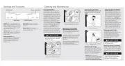
PLAN THE INSTALLATION
1. Locate the ventilator so the length of the duct
run and number of elbows needed are kept to a
minimum.
2. Where possible, ventilator should be centered
between wall studs or roof rafters.
3. Avoid pipes, wires, or other ductwork that may be
running through the wall.
ALL INSTALLATIONS
MODEL VOLTS AMPS CFM DUCT SIZE
DEV900 120 5.7 900 10 " DIA.
SPECIFICATIONS
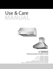
INSTALLER: Leave This Manual With The Homeowner
HOMEOWNER: Use And Care Information On Page 4
5. When cutting or drilling into wall, or ceiling, do not
damage electrical wiring or other hidden utilities.
6. Ducted fans must always be vented to the out-
doors.
7. To reduce risk of fire, use only metal ductwork.
8. This unit must be grounded.
READ AND SAVE THESE INSTRUCTIONS
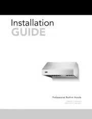
VIKING MODEL DEV900
EXTERIOR MOUNTED VENTILATOR
FOR USE WITH VCWH, VICH, DBCV, DICV, DCWH, DCWL, DCWN, DTWS AND
DCIH :-/-2+RANGE00' HOODS. 30" TO 42" WIDE, 9" TO 18" HIGH.
Produkspesifikasjoner
| Merke: | Viking |
| Kategori: | eksoshette |
| Modell: | DEV900 |
Trenger du hjelp?
Hvis du trenger hjelp med Viking DEV900 still et spørsmål nedenfor, og andre brukere vil svare deg
eksoshette Viking Manualer
26 September 2025
21 September 2025

21 September 2025
20 September 2025
20 September 2025
20 September 2025
20 September 2025
20 September 2025

20 September 2025

20 September 2025
eksoshette Manualer
- Toolcraft
- Hotpoint
- Caple
- Ariston Thermo
- Cata
- JennAir
- Ilve
- Roblin
- Exquisit
- Cecotec
- Electrolux
- ZLine
- Gram
- Coyote
- Thermador
Nyeste eksoshette Manualer

21 Oktober 2025

21 Oktober 2025
20 Oktober 2025
20 Oktober 2025
18 Oktober 2025
18 Oktober 2025
14 Oktober 2025

12 Oktober 2025
11 Oktober 2025
11 Oktober 2025