Behringer Ultrapatch PX1000 Bruksanvisning
Les nedenfor 📖 manual på norsk for Behringer Ultrapatch PX1000 (4 sider) i kategorien DJ-utstyr. Denne guiden var nyttig for 18 personer og ble vurdert med 4.5 stjerner i gjennomsnitt av 9.5 brukere
Side 1/4
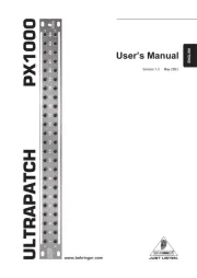
Version 1.2 2003 May
Users Manual
ENGLISH
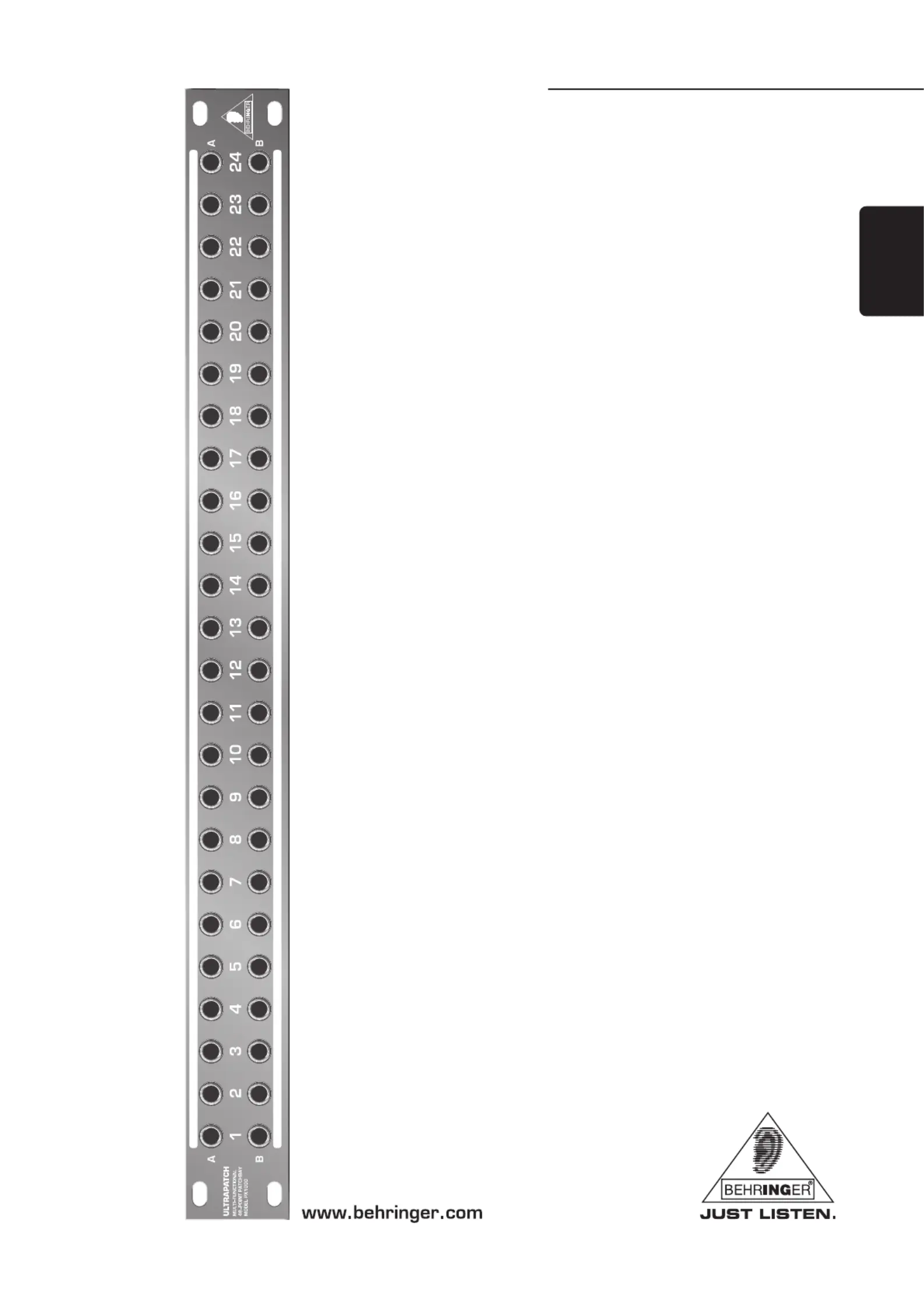
ULTRAPATCH PX1000
Produkspesifikasjoner
| Merke: | Behringer |
| Kategori: | DJ-utstyr |
| Modell: | Ultrapatch PX1000 |
Trenger du hjelp?
Hvis du trenger hjelp med Behringer Ultrapatch PX1000 still et spørsmål nedenfor, og andre brukere vil svare deg
DJ-utstyr Behringer Manualer
4 August 2025
4 August 2025

31 Januar 2025
DJ-utstyr Manualer
- NAD
- Ortofon
- Korg
- GOgroove
- Palmer
- Native Instruments
- Pyle
- Glorious
- Fun Generation
- Velleman
- BeamZ
- Tascam
- Omnitronic
- Line 6
- Saramonic
Nyeste DJ-utstyr Manualer
15 Oktober 2025
12 Oktober 2025
12 Oktober 2025
12 Oktober 2025
9 Oktober 2025
8 Oktober 2025
8 Oktober 2025

7 Oktober 2025

7 Oktober 2025

7 Oktober 2025