Biltema 20-0107 Bruksanvisning
Biltema
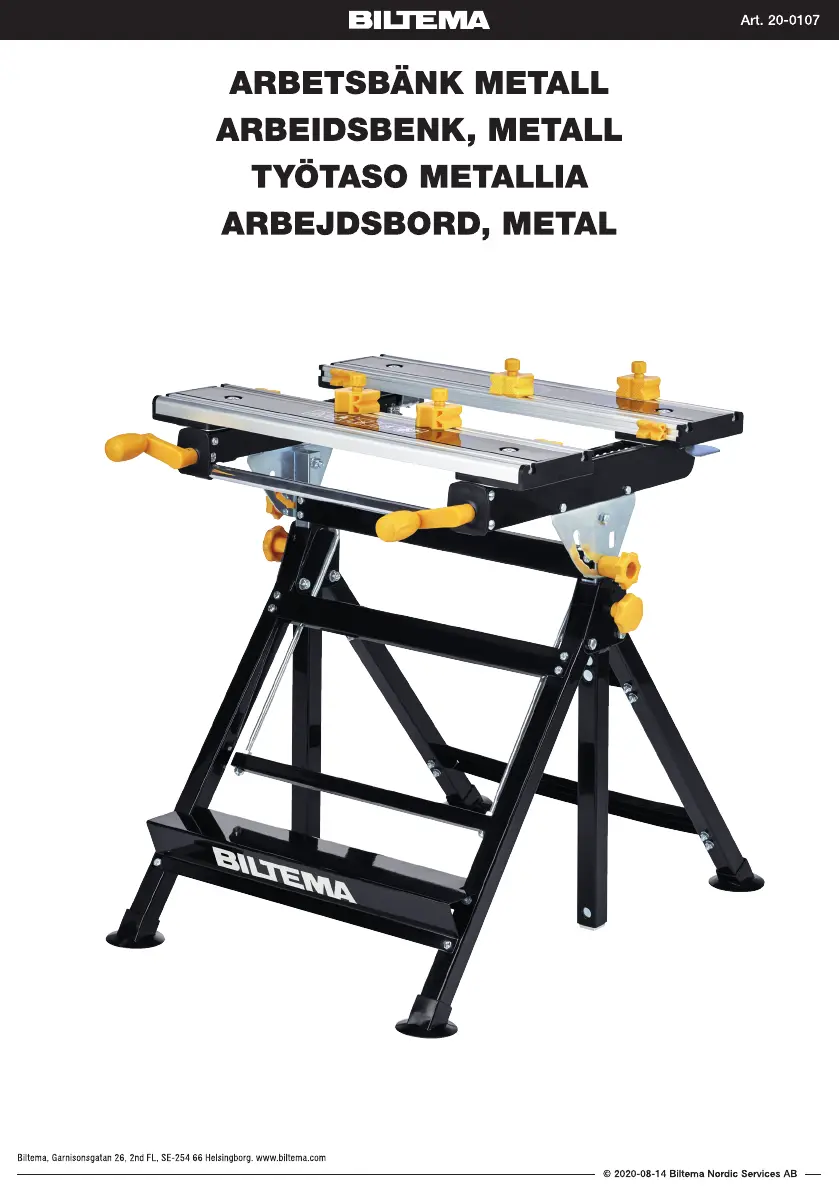
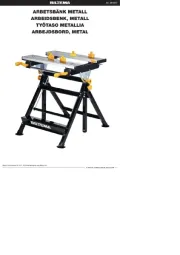
Arbeidsbenk
20-0107
Les nedenfor 📖 manual på norsk for Biltema 20-0107 (20 sider) i kategorien Arbeidsbenk. Denne guiden var nyttig for 8 personer og ble vurdert med 3.9 stjerner i gjennomsnitt av 4.5 brukere
Side 1/20
Produkspesifikasjoner
| Merke: | Biltema |
| Kategori: | Arbeidsbenk |
| Modell: | 20-0107 |
Trenger du hjelp?
Hvis du trenger hjelp med Biltema 20-0107 still et spørsmål nedenfor, og andre brukere vil svare deg
Arbeidsbenk Biltema Manualer
10 September 2025
10 September 2025
Arbeidsbenk Manualer
Nyeste Arbeidsbenk Manualer
23 September 2025

31 Januar 2025

31 Januar 2025

31 Januar 2025

31 Januar 2025

31 Januar 2025

31 Januar 2025

31 Januar 2025

31 Januar 2025

31 Januar 2025