Extron MLC 104 IP Plus AAP Bruksanvisning
Extron
Fjernkontroll
MLC 104 IP Plus AAP
Les nedenfor 📖 manual på norsk for Extron MLC 104 IP Plus AAP (6 sider) i kategorien Fjernkontroll. Denne guiden var nyttig for 21 personer og ble vurdert med 4.5 stjerner i gjennomsnitt av 2 brukere
Side 1/6

1
MLC 104 IP Plus Series • Setup Guide
The Extron MLC 104 IP Plus Series MediaLink
®
Controller integrates Ethernet connection into AV systems to allow users
to remotely control, monitor, and troubleshoot AV equipment, including display devices and switchers. It includes an
embedded web server, serial ports, and configurable digital I/O ports for use in applications that require control and
monitoring of multiple devices within an AV system.
The MLC 104 IP Plus series of controllers are configured using the free Extron Global Configurator (GC) software. The
MLCs integrate seamlessly with Extron GlobalViewer
®
Enterprise (GVE) software and the free GlobalViewer web-based AV
resource management softwarefor remote control applications. Global Configurator and other useful software applications
are available at www.extron.com.
A checklist of basic setup steps is provided at the end of this guide. For additional information see the help files and the
MLC 104 IP Plus Series User Guide, available at www.extron.com.
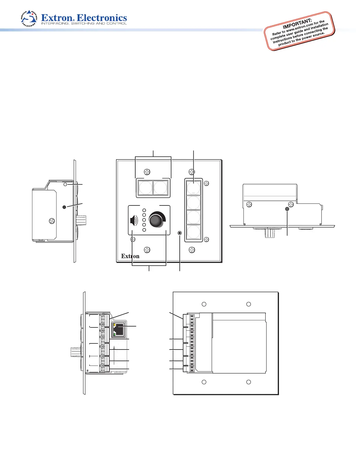
Panels and Features
123
GROUND
+V OUT
CM
GROUND
IR OUT
GROUND
SCP
GROUND
Tx
Rx
DISPLAY
RS-232/IR
A B C D E
COMM LINK
AB
MLS
RS-232
POWER
12V
DIGITAL
I/O
IR IN
Tx
GROUND
Rx
+12V IN
PRESS TAB WITH
TWEEKER TO REMOVE
LAN
P
RE
SS
TAB WIT
H
TWEEKER T
O
REM
O
V
E
LAN
CONFIG
DISPLAY
VOLUME
MLC 104 IP PLUS
ON
VCR
DVD
PC
OFF
1
2
3
4
RESET
RUN
100
IR
Right Side
Rear Panel
Left Side
Top Panel
Front
Panel
Display On and
Off Buttons
Volume Knob
and LEDs
IR Learning
Receiver
Config (RS-232
host control) Port
Input Selection
Buttons
LAN (IP) Port
Reset Button
(recessed)
Reset LED
Digital I/O Ports (3)
Power Input (12 VDC)
Control Module/IR/SCP
Port (COMM LINK)
Display or
Projector Control Port
MLS Switcher Port
Top Panel
Contents
MLC 104 IP Plus Series • Setup Guide 1
Panels and Features 1
Cabling and Features 2
Control — Projector or Display 2
Control — Control Modules,
SCP Control Panels (COMM Link Port) 2
Control — Digital Input or Output (I/O) 2
Control — MLS Switcher
(MLS RS-232 Port) 3
Power 3
Control — LAN (Ethernet) 3
Control — Serial (Cong) 4
About Global Congurator (GC) 4
What It Does 4
What To Set Up in GC 4
Conguration 5
Resources 5
Obtaining Control Drivers 5
Instructions, Information, and Assistance 5
Conguring for Network Communication 5
Network Conguration Options 5
Network Conguration Using ARP 5
Mounting 6
Setup Checklist: How to Proceed With Installation 6

2
MLC 104 IP Plus Series • Setup Guide (Continued)
Cabling and Features
Attach cables using the following wiring diagrams as a guide. Full details are available in the MLC 104 IP Plus Series User Guide.
CAUTION: Installation and service must be performed by authorized personnel only.
Control — Projector or Display
+V OUT
CM
GROUND
IR OUT
GROUND
SCP
Tx
Rx
DISPLAY
RS-232/IR
A B C D E
COMM LINK
IR IN
LAN
LAN
+
V
OUT
C
M
G R OUND
SCP
A B C D E
ABCDE
CO
MM LINK
IR
IN
Transmit (Tx)
Receive (Rx)
Ground ( )
RS-232 IR
Receive (Rx)
Transmit (Tx)
Ground ( )
Bidirectional
Projector or
Display
RS-232 Port
Projector
or Display
IR Receiver
or
(+)
(-)
(+)
(-)
(-)
(+)
Two Single IR Emitters
Ground ( )
IR Output Signal
Unidirectional
IR
Infrared:
• TTL level (0 to 5 V)
• Up to 1 MHz
Select RS-232 protocol via
software or SIS command.
Signals are bidirectional, ±5 V.
RS-232 default protocol:
• 9600 baud
• 8 data bits • 1 stop bit
• no parity • no flow control
NOTE: Each projector or display may
require different wiring. See the
manual that came with the projector
or display, or the Extron device driver
communication sheet for details.
Projector RS-232 / IR Port(s)
Right
Side
Panel
Control — Control Modules,
SCP Control Panels (COMM Link Port)
MLC
Right Side
Panel
123
GROUND
+V OUT
CM
GROUND
IR OUT
GROUND
SCP
Tx
Rx
DISPLAY
RS-232/IR
A B C D E
COMM LINK
DIGITAL
I/O
IR IN
PRESS TA
TWEEKER T
O
LAN
P
RE
SS
T
A
TWEEKER T
O
L
A
N
1
2
3
G R O UND
DIGITAL
DIGITAL
I/O
G
R
OU
ND
IR
OUT
T
x
R
x
DISPLAY
DISPLAY
R
S
-232
/
I
R
E
D
C
B
A
SCP communication (IR)
Ground ( )
IRCM, ACM, RCM
+12 VDC
C
B
A
Ground ( )
IRCM/ACM/RCM
+12 VDC
DVD & VCR CONTROL
PLAY NEXT/FWD PAUSE STOP
TUNER
Tx
PREV/REW
ENTER
TITLE MENU
TV/VCR
DVD VCR
IRCM-DV+
SCP 104
DISPLAY
VOLUME
SCP 104
ON
OFF
1
2
3
4
VIDEO
AUX
VIDEO
PC
IMAGE
MUTE
CM/IR/SCP Port
• SCPs: Tw o maximum per system
• Control modules: four maximum (four module addresses)
• To tal distance from port to last device: 200 feet (61 m) maximum
Control — Digital Input or Output (I/O)
RIght Side Panel
123
GROUND
+V OUT
CM
GROUND
IR OUT
GROUND
SCP
GROUND
Tx
Rx
DISPLAY
RS-232/IR
A B C D E
COMM LINK
AB
MLS
RS-232
POWER
12V
DIGITAL
I/O
IR IN
Tx
GROUND
Rx
+12V IN
PRESS TAB WITH
TWEEKER TO REMOVE
LAN
SS
TAB WIT
H
E
R T
O
REM
O
V
E
PR
E
TWEE
K
LAN
G
R
O
UN
D
A B
MLS
MLS
R
S-232
POWER
POWER
12
V
T
x
G
R
OU
N
D
R
x
+
12
V
IN
+
V
OUT
C
M
G
R
OU
N
D
I
R
OUT
G
R
OU
ND
SCP
T
x
R
x
DISPLAY
DISPLAY
RS-232/I
R
A B C D E
ABCDE
C
OMM LINK
IR
IN
Ground ( )
Digital I/O
Switch,
Sensor,
Relay
Digital I/O Ports
These three ports can be used as digital input or output, with or without +5 VDC pull-up.
Once configured, the digital input or output can monitor or trigger events and functions
(toggle relays, issue commands, send e-mail).

3
Control — MLS Switcher
(MLS RS-232 Port)
123
GROUND
+V OUT
CM
GROUND
SCP
GROUND
A B C D E
COMM LINK
AB
MLS
RS-232
POWER
12V
DIGITAL
I/O
IR IN
Tx
GROUND
Rx
+12V IN
PRESS TAB WITH
TWEEKER TO REMOVE
LAN
PRE
SS
TAB WIT
H
TWEEKER T
O
REM
O
V
E
L
A
N
G R O UND
POWER
POWER
12
V
+
12
V
IN
1
2
3
G
R O UND
+
V
OU
T
CM
G
R
OU
ND
SC
P
A B C D E
ABCDE
CO
MM LINK
DIGITAL
DIGITAL
I/O
IR
IN
Ground ( )
Transmit (Tx)
B
Receive (Rx)
A
Transmit (Tx)
Receive (Rx)
B
A
MLC/IR
ABC
Rear Panel
MLC/IR port
on MLS Switcher
Heat Shrink
Over Ground
or Drain Wires
Select RS-232 protocol via software or SIS
command. Signals are bidirectional, ±5 V.
RS-232 default protocol:
• 9600 baud • 8 data bits • 1 stop bit
• no parity • no flow control
NOTES:
• You must connect a ground wire
between the MLC and MLS.
• If you use cable that has a drain wire,
tie the drain wire to ground at both ends.
MLS Switcher RS-232 Port
MLC
Right
Side
Panel
Power
123
GROUND
SCP
GROUND
D E
LINK
AB
MLS
RS-232
POWER
12V
DIGITAL
I/O
IR IN
Tx
GROUND
Rx
+12V IN
PRESS TAB WITH
TWEEKER TO REMOVE
LAN
PRE
SS
TAB WIT
H
TWEEKER T
O
REM
O
VE
LAN
1
2 3
G
R
O
UND
SCP
D E
DE
LINK
A
B
MLS
MLS
RS
-232
DIGITAL
DIGITAL
I/O
IR IN
T
x
G
R
O
UN
D
R
x
Ground ( )
Ground
(ridged)
12 VDC
(smooth)
+12 VDC Input
Ground all devices.
External
Power Supply
(12 VDC, 1 A max.)
3/16"
(5 mm)
Max.
Power Input
• Connect to 12 VDC, 1 A power supply.
• Check the polarity of the power supply
wires before connecting it to the MLC.
• Front panel buttons light when the
MLC receives power.
Right
Side
Panel
Control — LAN (Ethernet)
MAC: 00-05-A6-XX-XX-XX
S/N:
Right Panel
123
GROUND
+V OUT
CM
GROUND
IR OUT
GROUND
SCP
GROUND
Tx
Rx
DISPLAY
RS-232/IR
A B C D E
COMM LINK
AB
MLS
RS-232
POWER
12V
DIGITAL
I/O
IR IN
Tx
GROUND
Rx
+12V IN
PRESS TAB WITH
TWEEKER TO REMOVE
LAN
PRE
SS
TAB WIT
H
TWEEKER T
O
REM
O
V
E
1
2
3
G
R
O
UND
+
V
OUT
C
M
G
R
OU
ND
I
R
OUT
G
R
OU
ND
SCP
G
R
O
UN
D
Tx
Rx
DISPLAY
DISPLAY
R
S
-232
/
I
R
A B C D E
ABCDE
CO
MM LINK
A
B
MLS
MLS
RS
-232
POWER
POWER
12
V
DIGITAL
DIGITAL
I/O
IR
IN
Tx
G R OUND
Rx
+ 12V IN
RJ-45
Connector
Insert Twisted
Pair Wires
Pins:
12345678
Link LED: Lights to indicate
a network connection.
Activity LED:
Blinks to indicate data
is being sent or received.
Ethernet (LAN)
Connect to an Ethernet network with a
straight through cable. This port must be
configured.
Default protocol:
• MLC IP address: 192.168.254.254
• Gateway IP address: 0.0.0.0
• Subnet mask: 255.255.0.0
• DHCP: off
• Link speed and duplex level: autodetected
MA
C Address
(on top
, and
on front panel
)
PC
TCP/IP
Network
Straight-through Cable
(for connection to a switch, hub, or router)
End 1 End 2
Pin Wire Color Pin Wire Color
1 white-orange 1 white-orange
2 orange 2 orange
3 white-green 3 white-green
4 blue 4 blue
5 white-blue 5 white-blue
6 green 6 green
7 white-brown 7 white-brown
8 brown 8 brown
Crossover Cable
(for direct connection to a PC)
End 1 End 2
Pin Wire Color Pin Wire Color
1 white-orange 1 white-green
2 orange 2 green
3 white-green 3 white-orange
4 blue 4 blue
5 white-blue 5 white-blue
6 green 6 orange
7 white-brown 7 white-brown
8 brown 8 brown
NOTE:
You must use this LAN port
to set up the MLC and
upload GC configuration
files and firmware. All
configuration can be
performed via this port.
Both ends use the TIA/EIA T568A wiring standard. Wire end 1 following the TIA/EIA T568A wiring standard,
wire end 2 with the T568B wiring standard.
Produkspesifikasjoner
Merke: | Extron |
Kategori: | Fjernkontroll |
Modell: | MLC 104 IP Plus AAP |
Trenger du hjelp?
Hvis du trenger hjelp med Extron MLC 104 IP Plus AAP still et spørsmål nedenfor, og andre brukere vil svare deg
Fjernkontroll Extron Manualer
16 Oktober 2024
16 Oktober 2024
16 Oktober 2024
16 Oktober 2024
16 Oktober 2024
16 Oktober 2024
16 Oktober 2024
Fjernkontroll Manualer
- Fjernkontroll ORNO
- Fjernkontroll Insignia
- Fjernkontroll LG
- Fjernkontroll Hama
- Fjernkontroll Neewer
- Fjernkontroll Philips
- Fjernkontroll Schwaiger
- Fjernkontroll Godox
- Fjernkontroll IKEA
- Fjernkontroll Samsung
- Fjernkontroll DJI
- Fjernkontroll One For All
- Fjernkontroll Sony
- Fjernkontroll Morel
- Fjernkontroll Vello
- Fjernkontroll Amewi
- Fjernkontroll Danfoss
- Fjernkontroll Pioneer
- Fjernkontroll Somfy
- Fjernkontroll Panasonic
- Fjernkontroll Audio-Technica
- Fjernkontroll Wet Sounds
- Fjernkontroll PeakTech
- Fjernkontroll Technisat
- Fjernkontroll Velleman
- Fjernkontroll Nanlite
- Fjernkontroll DataVideo
- Fjernkontroll Nexa
- Fjernkontroll Aplic
- Fjernkontroll CSL
- Fjernkontroll Omega
- Fjernkontroll Tripp Lite
- Fjernkontroll Zalman
- Fjernkontroll Canon
- Fjernkontroll Blaupunkt
- Fjernkontroll Conceptronic
- Fjernkontroll Intermatic
- Fjernkontroll Mosconi
- Fjernkontroll Reely
- Fjernkontroll Infinity
- Fjernkontroll Logilink
- Fjernkontroll Majestic
- Fjernkontroll Ridem
- Fjernkontroll Spektrum
- Fjernkontroll Nikon
- Fjernkontroll Antelope Audio
- Fjernkontroll Vaddio
- Fjernkontroll Abus
- Fjernkontroll Vizio
- Fjernkontroll Russound
- Fjernkontroll CGV
- Fjernkontroll Libec
- Fjernkontroll Profoto
- Fjernkontroll Impact
- Fjernkontroll PDP
- Fjernkontroll Uni-T
- Fjernkontroll Rademacher
- Fjernkontroll Vimar
- Fjernkontroll Genaray
- Fjernkontroll Biltema
- Fjernkontroll Harman Kardon
- Fjernkontroll Ferguson
- Fjernkontroll Compustar
- Fjernkontroll Savio
- Fjernkontroll Ardes
- Fjernkontroll Conrad
- Fjernkontroll Ruwido
- Fjernkontroll Antec
- Fjernkontroll Parkside
- Fjernkontroll Magnus
- Fjernkontroll Multibrackets
- Fjernkontroll MIOPS
- Fjernkontroll EQ-3
- Fjernkontroll Kathrein
- Fjernkontroll Autel
- Fjernkontroll AV:link
- Fjernkontroll Interphone
- Fjernkontroll Geemarc
- Fjernkontroll Futaba
- Fjernkontroll Metronic
- Fjernkontroll SMK-Link
- Fjernkontroll Pentatech
- Fjernkontroll Hannspree
- Fjernkontroll Lutron
- Fjernkontroll TELE System
- Fjernkontroll Pixel
- Fjernkontroll Viper
- Fjernkontroll Bang Olufsen
- Fjernkontroll FireAngel
- Fjernkontroll Fusion
- Fjernkontroll Control4
- Fjernkontroll Hegel
- Fjernkontroll Essentiel B
- Fjernkontroll URC
- Fjernkontroll Canal Digitaal
- Fjernkontroll AXIL
- Fjernkontroll Irradio
- Fjernkontroll Funai
- Fjernkontroll MKC
- Fjernkontroll REV
- Fjernkontroll Phoenix Technologies
Nyeste Fjernkontroll Manualer
Viper XpressKit 508D Double-Guard Proximity Sensor Bruksanvisning
15 September 2025
15 September 2025
15 September 2025
14 September 2025
12 September 2025
11 September 2025
9 September 2025
8 September 2025
8 September 2025
8 September 2025