Fantini Cosmi L23EM1A Bruksanvisning
Fantini Cosmi
Termostat
L23EM1A
Les nedenfor 📖 manual på norsk for Fantini Cosmi L23EM1A (2 sider) i kategorien Termostat. Denne guiden var nyttig for 39 personer og ble vurdert med 4.5 stjerner i gjennomsnitt av 20 brukere
Side 1/2

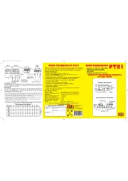
To get access to the parameter configuration menu, press button ■ + for 5 seconds.
With button ■ select the parameter to be modified. or
Press button ■ to display the value.
By keeping button ■ pressed, use button to set the desired value. or
When button ■ is released, the newly programmed value is stored and the following parameter is displayed.
To exit from the setup, press button ■ or wait for 30 seconds.
PAR RANGE DESCRIPTION
SCL 1°C;
2°C;
°F
Readout scale (see table of input specifications)
Caution: upon changing the value, it is then absolutely necessary to the param-SCL reconfigure
eters relevant to the absolute and relative temperatures ( , , , etc..)SPL SPH 1SP 1HY
SPL -50°...SPH Minimum limit for setting1SP
SPH SPL...150° Maximum limit for setting.1SP
1SP SPL... SPH Setpoint (value to be maintained in the room).
1CM HY; PID Control mode.
With =H you select control with hysteresis: parameters , are used.1CM Y1HY 1T0 1T1 and
With =PID you select a Proportional-Integral-Derivative control mode: parameters , , 1CM 1PB 1IT
1DT 1AR 1CT, , will be used
1CH REF; HEA Refrigerating (REF) or Heating (HEA) control mode.
1CM=HY
1HY 0...19.9° OFF/ON thermostat di ferential. With =0 the output is always of 1HY .
1T0 0...30min Minimum o f time.f
After output been turned f, it remains inactive minutes 1 has of for 1T0 regardless of the
temperature value measured.
1T1 0...30min Minimum on time. ( ).the following parameter will be 1PF
After output 1 has been turned on, it remains active for 1T1 minutes regardless of the temperature
value measured.
1CM=PID
1PB 0...19.9° Proportional bandwidth.
Temperature takes by changing control place the
ON of the the closer the time output: temperature
to the the less of setpoint, time activation. A small
proportional band increases the promptness of
response of the to system temperature variations,
but make it stable. A tends to less purely
proportional stabilises temperature control the
within proportional band but the does not cancel
the deviation from setpoint.
With =0 the output is always o1PB .
1IT 0...999s Integral action time.
The error cancelled an steady-state is by inserting
integral action. integral action time, determines The
the speed the with which steady-state temperature
is achieved, but high ( low) may be a speed 1IT the
cause overshoot instability in of and the response.
With =0 the integral control is disabled.1IT
1DT 0...999s Derivative action time.
Response overshoot may be reduced by inserting
a derivative Action. A high derivative action (1DT
high) makes system very sensitive the to small
temperature variation causes instability s and . With
1DT=0 the derivative control is disabled.
1AR 0...100% Reset of integral action time referred to 1PB
Decreasing reduces integral action zone, consequently the parameter 1AR the control and the
overshoot (see figure on paragraph ).1IT
1CT 1...255s Cycle time.
It’s the the ON changes. The the to controlled period in which output time quicker system be
reacts to the smaller the order to temperature variations, cycle time must be, in obtain higher
temperature stability and less sensitivity to load variations.
1PF ON/OFF Output state in case of probe failure.
OAU NON;
THR;
AL0;
AL1
AUX output operation.
NON : output disabled (always o f). (fthe next parameter will be ATM)
THR: output programmed for second thermostat control ( ).the next parameter will be 2SM
AL0: contacts open when an alarm condition occurs (the next parameter will be ATM).
AL1: contacts make when an alarm condition occurs (the next parameter will be ATM).
OAU=THR
2SM ABS;
REL
Setpoint 2 mode.
Channel ma 2 et s point y be ab olus te (2SM=ABS , ) or a di teren ial t erela iv t s t o etpoin 1 (2SM=REL)
2SM=ABS
2SP SPL...SPH Auxiliary output switchover temperature ( )the next parameter will be 2CH
2SM=REL
2DF -19.9...19.9° Temperature di ferential relative to The auxiliary output setpoint is equal to f1SP. 1SP 2DF+
ON/OFF refrigerating control
( =H1CM Y, =REF)1CH
ON/OFF heating control
( =H1CM Y, =HEA)1CH
1SP 1SP+1HY T[°]
ON
OFF
1SP1SP-1HY T[°]
ON
OFF
Time
Temperature
Process
temperature
Overshoot Steady-state error
1PB
1SP
Time
Temperature
Process
temperature
Overshoot
1PB1PBx1AR%
integral control
action area
1SP
Time
Temperature
Process
temperature
Overshoot
1PB
1SP
2SP 2SP+2HY T[°]
ON
OFF
2SP2SP-2HY T[°]
ON
OFF
ON/OFF control in refrigeration
( =ABS, =REF)2SM 2CH
ON/OFF control in heating
( =ABS, =HEA)2SM 2CH
1SP+2DF
1SP
2DF>0 1SP+2DF+2HY T[°]
ON
OFF
1SP
1SP+2DF
2DF<0
1SP+2DF-2HY T[°]
ON
OFF
ON/OFF control in refrigeration. Setpoint 2
relative to setpoint 1 ( =THR, =REF)OAU 2CH
ON/OFF control in heating. Setpoint 2
relative to setpoint 1 ( =THR, =HEA)OAU 2CH
Power supply
L03BI- 12Vac/dc ±10%, 3W
L03BM- 230 Vac±10%, 50/60Hz, 3W
Relay outputs (L03B---)
OUT1 16(4)A 240Vac
OUT2 16(4)A 240Vac
Inputs
see table of input specifications
Measurement range
see table of input specifications
Measurement accuracy
see table of input specifications
Operating conditions
-10 … +50°C; 15%...80% r.H.
CE (Reference Norms)
EN60730-1; EN60730-2-9;
EN55022 (Class B); EN50082-1
Front protection
IP40
OAU=THR
2CH REF; HEA Refrigerating control (REF) or heating control mode (HEA) for the auxiliary output.
2HY 0...19.9° Di ferential of thermostat 2. With =0 the auxiliary output always remains of2HY .
2T0 0...30min Minimum o f time.f
After output 2 has been turned of f, it remains inactive for 2T0 minutes regardless of the temperature
value measured.
2T1 0...30min Minimum on time.
After output 2 has been turned on, it remains active for 2T1 minutes regardless of the temperature
value measured.
2PF ON/OFF Auxiliary output state in case of probe failure.
ATM NON;
ABS;
REL
Alarm hre hold managemen t s t.
NON t : all empera t ure alarms are ed inhibit (t t he ollowing f parame er will be SB).
ABS: t vhe alues programmed in ALA A and AH s srepre en het t real alarm hre t holds.
REL: the programmed values in ALR and AHR are alarm diff teren ials tre erredf o 1SP and 1SP Y+1H .
ATM=ABS
ALA -50°...AHA Low temperature alarm threshold.
AHA ALA...150° High temperature alarm threshold.
ATM=REL
ALR -12.0...0° Low temperature alarm di ferential. f
With =0 the low temperature alarm is excludedALR
AHR 0...12.0° High temperature alarm di ferential. f
With =0 the high temperature alarm is excludedAHR
ATD 0...120min Delay before alarm temperature warning.
SB NO/YES Stand-by button enabling.
INP 0mA/4mA,
T1/T2
ST1/SN4
Sensor input selection (see table of input specifications).
Warning: “0mA/4mA”, “T1” and “T2” are not available
RLO -19.9...RHI Minimum range value
RLO takes the minimum value measured by the transmitter (i.e. the value matching 0V, 0/4mA).
RHI RLO...99.9 Maximum range value
RHI takes the maximum value measured by the transmitter (i.e. the value matching 1V, 20mA)
OS1 -12.5...12.5° T1 oset.Probe
TLD 1...30min Delay for minimum temperature (TLO) and maximum temperature (THI) logging.
SIM 0...100 Display slowdown
ADR 1...255 address for PC communication (not available)
1SP
1SP-ALR
T[°]
ON
OFF
1SP+1HY+AHR
1SP1SP-1HY-ALR 1SP+AHR
T[°]
ON
OFF
Temperature alarm with relative thresholds,
refrigerating control (ATM 1CH=REL, =REF)
Temperature alarm with relative thresholds,
heating control (ATM 1CH=REL, =HEA).
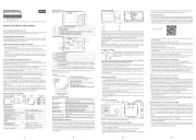
L03BM--
1112
230V~
OUT2
18 17 16
OUT1
21 20 19
2 3
16(4)A16(4)A
DISPLAY
During normal operation, the display shows either the temperature measured or one of the following indications:
Controller in stand-by Controller in autotuning
Probe T1 overrange or failure In tuning: timeout1 error
Room high temperature alarm In tuning: timeout2 error
Room low temperature alarm In tuning: overrange error
MENU INFO
The information available in this menu is:
Maximum temperature recorded Keypad state lock
Minimum temperature recorded
Access to menu and information displayed.
Press and immediately release button ■.
With button ■ select the data to be displayed. or
Press button ■ to display value.
To exit from the menu, press button ■ or wait for 10 seconds.
Reset of THI, TLO recordings
With button ■ select the data to be reset. or
Display the value with button ■.
While keeping button ■ pressed, use button .
CHANNEL 1 SETPOINT (display and modification of desired temperature value)
P se re andss relea
bu
tt
on
■ L : the
ED s 1L1 blinks, the di play shows SP 1 ec et a oc t for s ond and hen he t t s point ss ia ed value.
P ress buttons■ o or t se het t desired value (adjus is witment thin minimum the SPL and maximum SPH tlimi ).
To store the new value press button ■ , or wait for 10 seconds.
To go back to normal mode without saving the new value, press ■.
CHANNEL 2 SETPOINT
With auxiliary output ( the set as thermostat control ■ =THR), it possible modify setpoint during operation OAU ’s to 2 the normal
of the controller.
Press and release button ■ : LED L2 blinks, display shows 2S if setpoint is absolute the the P for 1 second 2 an threshold
( =ABS), alternatively display shows2SM the 2DF, if setpoint is relative setpoint ( =REL), value 2 a threshold to 1 2SM then the
associated to the parameter appears.
Press buttons ■ to set the desired value. or
To store the new value press button ■ or wait for 10 seconds.
To go back to normal mode without saving the new value, press ■.
STAND-BY
B
u
tt ss fon , when pre ed or 3 second he on rollers, allows t c t to be pu t on a standby tor ou put tcon rolt o be resumed (wi th SB=YES only).
KEYPAD LOCK
The attempted the controllers keypad lock avoids undesired, potentially dangerous operations, which might be when is operating
in public menu, =YES inhibit functions buttons. a place. In the INFO set parameter LOC to all of the To normal resume operation
of keypad, adjust setting so that LOC=NO.
CONTROLLER AUTOTUNING IN PID MODE
Before starting
In the mode set =PID; that matches the mode setup (see configuration parameters): 1CM make sure 1CH desired operation
( =REF for refrigerating control, =HEA for heating control); then adjust setpoint at the desired value.1CH 1CH 1SP
Start autotuning
During operation, keep buttons 3 blinks display normal + pressed for seconds. 1CT on the . + or set the With cycle
time in define dynamic be order to the of the process to controlled. To the press ; to start abort autotuning function, autotuning
press + or wait for 30 seconds.
During autotuning
During entire autotuning phase, display TUN with actual temperature measured. power failure, the the alternates the In case of
when power is resumed, initial autotest phase, resumes autotuning function. after the the controller the To the abort autotuning,
without modifying previous parameters, keep button the control pressed for seconds. the has place 3 After autotuning taken
successfully, the controller updates the control parameters and start to control.
Errors
If the autotuning function failed, the display shows an error code:
E1 the controller not the the Increase timeout1 error: could bring temperature within proportional band.■ in heating 1SP case of
control, vice versa, decrease in case of refrigerating control and re-start the process.1SP
E2 the has not ended the Re-start the timeout2 error: autotuning within maximum time allowed (1000 cycle times). autotuning ■
process and set a longer cycle time 1CT.
E3 temperature overrange: check was caused by probe malfunction, that the error not a then decrease ■ in heating 1SP case of
control, vice versa increase in case of refrigerating control and then re-start the process.1SP
To eliminate the error indication and return to the normal mode, press button ■.
Control improvement
To reduce overshoot, reduce the integral action reset ■1AR
To increase the
response speed
o
f t the em syst, reduce
he propor
t
ional band
.e
To reduce swings in steady-state temperature, increase integral action time the
■ system stability1IT;
is thus increased, although
its response speed is decreased.
To the speed of response to the the increase variations in temperature, increase derivative action time ■ Caution: high 1DT. a
value makes the system sensitive to small variations and it may be a source of instability.
RECALIBRATION
Have a precision reference thermometer or a calibrator to hand. Ensure that ■ =0 and =0.OS1 SIM
Switch the controller o f then on again.f ■
During the auto-test phase, press buttons ■ and keep them pressed till the controller shows + 0AD.
With buttons ■ : allows calibration 0, inserting correction over whole and select or 0AD SAD 0AD a of a constant the scale
of a of the top part of the scale a the measurement. SAD allows calibration measurement with proportional correction between
calibration point and 0.
Press ■ to the and then + or to the read the the display value use make value coincide with value measured by
reference instrument.
Exit from calibration by pressing button ■.
The
L03B--
controller
, size 71x98x61 (WxHxD), is be secured rail in such position ensure liquid mm to to a DIN a as to that no
infiltrates causing serious damage and compromising safety;
Make sure electrical connections comply with “wiring diagrams”. that the paragraph To the eects of reduce electromagnetic ■
disturbance, keep the sensor and signal cables well separate from the power wires.
Place the probe T1 inside the room in a point that truly represents the temperature of the stored product. ■
OUT1
OUT2
L1
L2
Channel 1 output
Channel 2 output
Alarm
Channel 1 setpoint modification
Channel 2 setpoint modification
Fig.1 - Front panel
Thank you for having chosen a Fantini Cosmi product. Before installing the instrument, please read these instructions carefully
to ensure maximum performance and safety.
L03B--/L23EM1A INSTRUCTION FOR USE
Info / Enter button Modify Setpoint 1 / Decrease button
Increase / Modify Setpoint 2 button Exit / Stand-by button
MODEL INPUT
RANGE [MEASUREMENT ACCURACY]
SCL=1°C SCL=2°C SCL=°F
L03B--
INP=ST1 PTC 1000 Ω
(LS120)
-40/-19.9 ÷ 99.9/105°C
[<±0.3°C(-40÷130°),±1°C]
-40 ÷ 105°C
[<±0.3°C (-40÷130°),±1°C]
-40 ÷ 221°F
[<±0.6°F (-40÷221°),±2°F]
INP=SN4 NTC 10K Ω
(LS130)
-40/-19.9 ÷ 99.9/105°C
[<±0.3°C(-40 100÷ °), ±1°C]
-40 ÷ 105°C
[<±0.3°C (-40÷100°),±1°C]
-40 ÷ 221°F
[<±0.6°F (-40÷210°),±2°F]
Via Dell’Osio 6
20090 Caleppio di Settala MI ITALIA
Phone no. +39 02 95682.222
Fax no. +39 02 95307006
Web: www.fantinicosmi.it
e-mail: export@fantinicosmi.it
AC1-5
L03BI--
1112
12Vac/dc
OUT2
18 17 16
OUT1
21 20 19
2 3
16(4)A16(4)A
L23EM1A
12 11
230V~
OUT1
21 20 19
rH
V
2 3 4
VIN V+V-
16(4)A
L23EM1A 0÷1V (LS160A) RLO÷RHI [< ± 3mV] -----
Produkspesifikasjoner
| Merke: | Fantini Cosmi |
| Kategori: | Termostat |
| Modell: | L23EM1A |
Trenger du hjelp?
Hvis du trenger hjelp med Fantini Cosmi L23EM1A still et spørsmål nedenfor, og andre brukere vil svare deg
Termostat Fantini Cosmi Manualer

2 April 2025

2 April 2025

2 April 2025

2 April 2025

2 April 2025

2 April 2025

27 Oktober 2024

27 Oktober 2024

27 Oktober 2024

27 Oktober 2024
Termostat Manualer
- Bticino
- Vaillant
- Emko
- Somfy
- Velleman
- Maico
- Oregon Scientific
- Watts
- Hager
- Seitron
- GE
- Niko
- Go Green
- Inkbird
- Finder
Nyeste Termostat Manualer
19 Oktober 2025

19 Oktober 2025

9 Oktober 2025

8 Oktober 2025

6 Oktober 2025
6 Oktober 2025
6 Oktober 2025
24 September 2025

24 September 2025
24 September 2025