GENERAL Life HT11S Bruksanvisning
GENERAL Life
Termostat
HT11S
Les nedenfor 📖 manual på norsk for GENERAL Life HT11S (2 sider) i kategorien Termostat. Denne guiden var nyttig for 15 personer og ble vurdert med 4.6 stjerner i gjennomsnitt av 8 brukere
Side 1/2
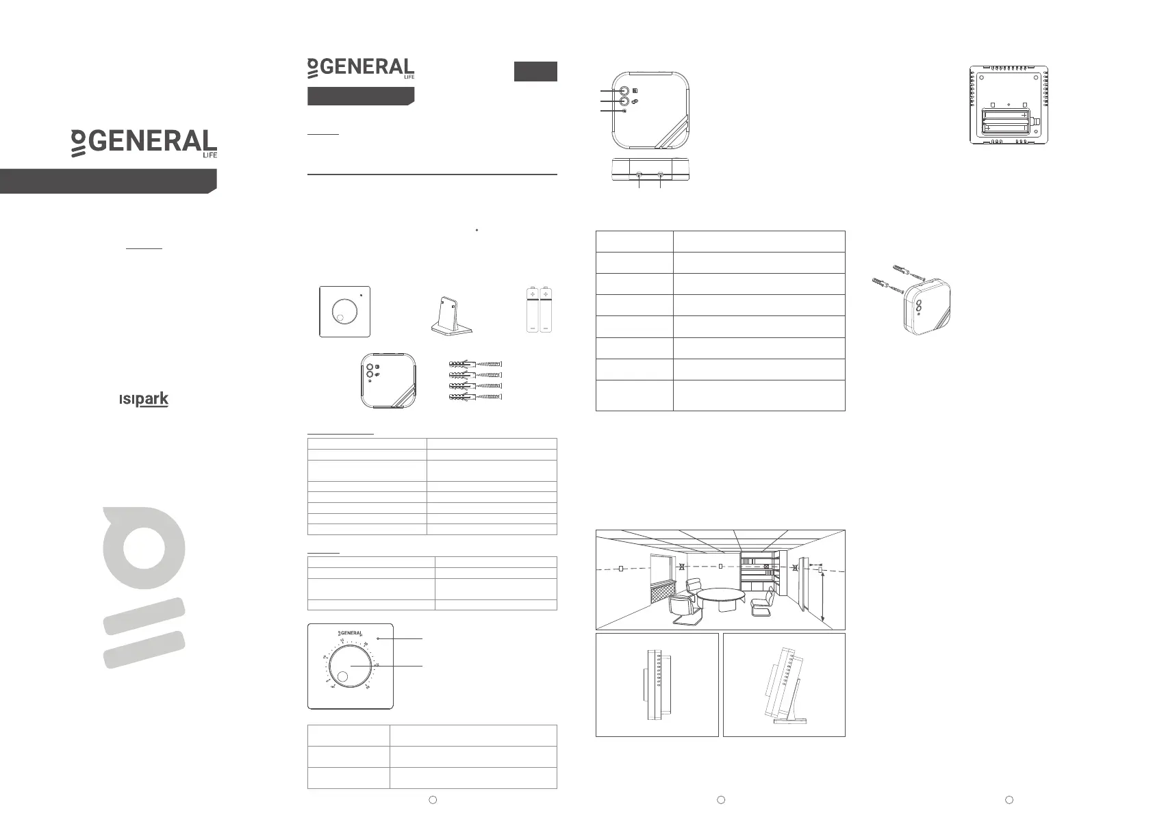
BATTERY PLACEMENT
Remove the battery cover located on the back of your Room
Thermostat. Insert 2 new AAA alkaline batteries into the battery
housing with the correct battery direction and close the battery cover.
Replace both batteries at the same time.
WARNING!
When the product is not used for a long period (more than 15 days),
remove the batteries. Otherwise, malfunctions that may occur would
be out of warranty.
Please throw your dead batteries into the waste bin for batteries.
RECEIVER PLACEMENT
The important things to note for the Receiver
placement is avoiding physical contact between
the Receiver and boiler, and protecting it against
materials such as liquid,dust etc.
The devices should be placed in order to minimize the damage to the
received and transmitted signals by paying attention to the following
points;
The devices should not be mounted on metal surfaces.
The devices should not be installed close to electrical cables and
electronic equipment such as computers and television units.
The devices should not be installed near large metal structures or
other building materials using fine metal meshes such as special
glass or special concrete.
Distance between the Room Thermostat and the Receiver should
not exceed 20 meters or 2 floors.
Receiver must be installed at least 50 cm away from the boiler.
RECEIVER SETUP
First, shut down your boiler and your boiler's power source with all
electrical current (fuse,socket etc.)
As shown in the connection diagram, connect one end of the boiler
connection cable to the COM and the other to the NO input.of the
Receiver.
Connect the other ends of the cable -which you connected to the
Receiver- to room thermostat connection terminal as shown in your
boiler's user manual.
You must first connect the Receiver power cable to the Receiver
and then to the fuse to which the boiler is connected.
After completing the cable connection process,firstly turn on your
fuse and then your boiler.
By pressing the Receiver's manual usage button for 2 seconds, you
should see the Orange Light blinking on the Receiver. In this way,
after making sure that the boiler is operating, press the same button
again for 2 seconds and see that the Orange LED turns off.
Set up the Room Thermostat to pair the Receiver with the Room
Thermostat.
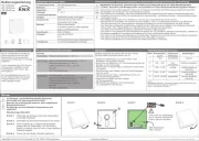
RECEIVER
RECEIVER LED DESCRIPTIONS
ROOM THERMOSTAT PLACEMENT
Room Thermostat needs to be placed in the room which is used most
frequently. For instance; living room or lounge. Placing the Room
Thermostat in a spot that have air circulation like entrance of a room
or side of window should be avoided. Also anywhere close to heating
units such as radiator, stove and spots which get direct sun lights
would not be suitable. Room Thermostat needs to be located above
the floor 150 cm height. Few trials may be made to find the most
convenient spot.
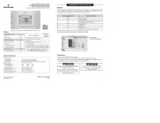
GENERAL SPECIFICATIONS
HT10 RF/HT10S RF/HT11S RF is a wireless room thermostat. The
user can adjust the room temperature with the required temperature
and get more comfortable and economic heating.
Precise Temperature Measurement Wireless Connection
ON/OFF Control
HT10 RF/HT10S RF/HT11S RF AND EQUIPMENTS
TECHNICAL DATA
Room Thermostat
Receiver
ROOM THERMOSTAT
Room Thermostat Indicator LED Descriptions
1
2 3
Room Thermostat
generallife.com.tr
85.7mm / 85.7mm / 33.5mm
3V DC (2 x AAA alkaline battery)
o
0.1 C
o
0.3 C
o o
(5 C) – (30 C)
1 Year (2 x AAA)
o o
(-10 C) – (+50 C)
o o
(-20 C) – (+60 C)
Alkaline
Battery
AAA
AAA
Room Thermostat sends a close signal to the
Receiver and the heating unit stops operating.
Room Thermostat sends an open signal to
the Receiver and the heating unit starts.
Room Thermostat sends a pairing signal to
the Receiver.
If it blinks once
If it blinks twice
If it blinks three times
Dimensions ( H / L / W )
Operating Current
Temperature Measurement
Accuracy
Operating Sensivity
Operating Temperature Range
Battery Life
Operating Temperature
Storage Temperature
1-Manual Operation Button:
By disabling the Receiver, it enables you
to use your boiler manually.
2-Pairing Button:
Allows to pair the Receiver with the
Room Thermostat.
3-Receiver LED Light
4-Receiver Power Cable Input
5-Boiler Connection Cable Input
150 cm
min.20 cm
Holder
Dowels and Screws
Receiver
90mm / 90mm / 25mm
230V AC
7A (240VAC – Resistive load)
10A (120VAC – Resistive load)
o o
(-20 C) – (+60 C)
Dimensions
Operation Current
Relay NO Switching Current
Storage Temperature
4
1
2
3
5
Adjustment Knob
Indicator LED
generallife.com.tr
DIGITAL ROOM THERMOSTAT
Steady Red
Blinking Green
Steady Green
3 Short Orange
Blinking
Steady Orange
3 Short Green
Blinking
Blinking Orange
Blinking Red
Receiver has power but Receiver and
Room Thermostat are not paired.
Waiting for pairing signal from Room Thermostat.
Receiver and Room Thermostat are paired.
Boiler is not operating.
Operate the boiler signal has reached to the
Receiver.
Boiler is operating.
Shut the boiler down signal has reached to the
Receiver.
Boiler is operating in manual mode.
Receiver did not get a signal from the
Room Thermostat for 22 minutes or longer and
boiler has shut down.
ENGLISH
DIGITAL ROOM THERMOSTAT
SERIES:
MITRA, ARUNA, CERES, GAIA,
ILLONA, NORA, SENNA, THERMA
HT10 RF/HT10S RF/HT11S RF
USER MANUALS
HT10 RF/HT10S RF/HT11S RF USER MANUAL
SERIES:
MITRA, ARUNA, CERES, GAIA, ILLONA, NORA, SENNA, THERMA
Produkspesifikasjoner
| Merke: | GENERAL Life |
| Kategori: | Termostat |
| Modell: | HT11S |
Trenger du hjelp?
Hvis du trenger hjelp med GENERAL Life HT11S still et spørsmål nedenfor, og andre brukere vil svare deg
Termostat GENERAL Life Manualer
24 September 2025
24 September 2025

10 Desember 2024

10 Desember 2024

10 Desember 2024

10 Desember 2024

10 Desember 2024

10 Desember 2024

10 Desember 2024

10 Desember 2024
Termostat Manualer
- Enda
- Intellinet
- AWB
- REMKO
- Panasonic
- Computherm
- OJ ELECTRONICS
- Chacon
- Hunter
- Truma
- Xavax
- Devi
- Otio
- HomePilot
- Watts
Nyeste Termostat Manualer
19 Oktober 2025
19 Oktober 2025

9 Oktober 2025
8 Oktober 2025
6 Oktober 2025
6 Oktober 2025
6 Oktober 2025

24 September 2025

15 September 2025
12 September 2025