Franke PES-PD-SNI Bruksanvisning
Les nedenfor 📖 manual på norsk for Franke PES-PD-SNI (28 sider) i kategorien Kran. Denne guiden var nyttig for 31 personer og ble vurdert med 3.6 stjerner i gjennomsnitt av 16 brukere
Side 1/28
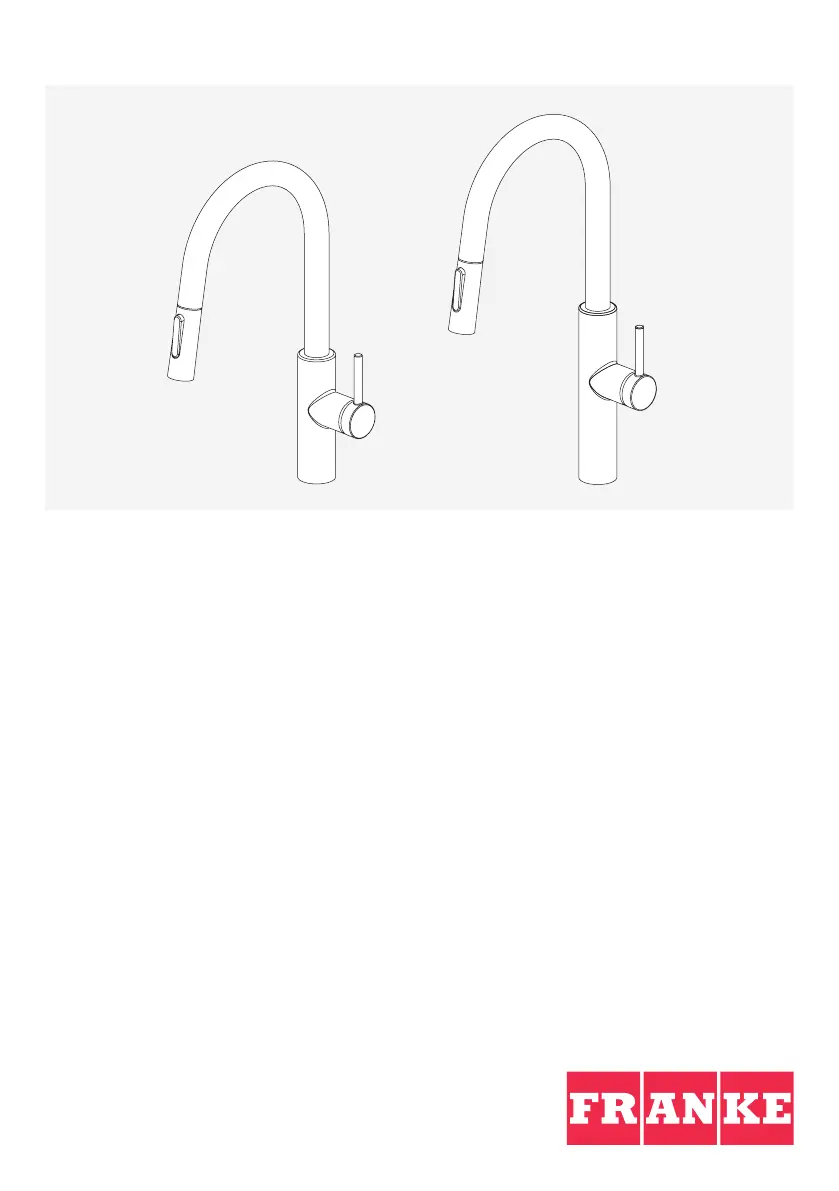
Pescara
EN Installation manual Kitchen Faucet
ES Manual de instalación Grifo de cocina
FR Manuel d‘installation Robinet de cuisine
PES-PD-CHR PES-PD-MBK PES-PD-SNI
PES-PDX-CHR PES-PDX-SNI
Produkspesifikasjoner
| Merke: | Franke |
| Kategori: | Kran |
| Modell: | PES-PD-SNI |
Trenger du hjelp?
Hvis du trenger hjelp med Franke PES-PD-SNI still et spørsmål nedenfor, og andre brukere vil svare deg
Kran Franke Manualer
2 August 2025

7 Januar 2025

4 Januar 2025

4 Januar 2025

4 Januar 2025

4 Januar 2025

4 Januar 2025

27 Desember 2024

22 Oktober 2024

15 Oktober 2024
Kran Manualer
- Axor
- Peerless-AV
- Somfy
- Biltema
- Graff
- Concept
- Sloan
- IKEA
- Livarno Lux
- Elkay
- Rogerseller
- Vestil
- Sussex
- Krowne
- Smeg
Nyeste Kran Manualer

13 Oktober 2025

13 Oktober 2025

13 Oktober 2025

13 Oktober 2025

13 Oktober 2025

13 Oktober 2025

13 Oktober 2025

13 Oktober 2025

13 Oktober 2025

13 Oktober 2025