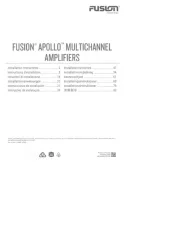
Fusion Apollo MS-AP12OOO Bruksanvisning
Les nedenfor 📖 manual på norsk for Fusion Apollo MS-AP12OOO (33 sider) i kategorien Mottaker. Denne guiden var nyttig for 11 personer og ble vurdert med 4.5 stjerner i gjennomsnitt av 6 brukere
Side 1/33
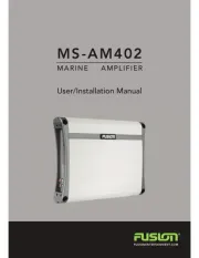
A Garmin Brand
FUSION®
APOLLO™
MS-AP12OOO
MONOBLOCK
AMPLIFIER
Installation
Instructions
....................... 2
lnstallatie-instructies
.........................
39
Instructions
d'installation
..................... 7
lnstallationsvejledning
.......................
45
lstruzioni
di
installazione
...................
13
Asennusohjeet
..................................
51
lnstallationsanweisungen
..................
20
I
nstalleringsinstruksjoner
...................
56
lnstrucciones
de
instalaci6n
..............
27
lnstallationsinstruktioner
...................
62
lnstru96es
de
instalac;ao
....................
33
~~+~-
~~11=1
iJ"'
.........................................
68
Garmin
•,
the
Garmin
logo,
Fusion
•,
Fusion
-
Link
",
and
the
Fusion
logo
are
trademarks
of
Garmin
Ltd
.
or
its s
ubsidiarie
s,
regi
s
tered
in
the
USA
and
other
countries
.
The
se
trademarks
may
not
be
used
without
the
express
permission
of
Garm
in.
M/N
:
A03876
Printed
in
Taiwan~-.,
February 2023
190-02849-0I_0A
Produkspesifikasjoner
| Merke: | Fusion |
| Kategori: | Mottaker |
| Modell: | Apollo MS-AP12OOO |
Trenger du hjelp?
Hvis du trenger hjelp med Fusion Apollo MS-AP12OOO still et spørsmål nedenfor, og andre brukere vil svare deg
Mottaker Fusion Manualer
5 September 2025
4 September 2025
3 September 2025
3 September 2025
3 September 2025
3 September 2025
2 September 2025
2 September 2025
2 September 2025
2 September 2025
Mottaker Manualer
- Blustream
- Elsys
- AVMATRIX
- Appsys ProAudio
- Atlas
- Metra
- Max
- IFi Audio
- Proel
- Kathrein
- Pyle
- Audiotec Fischer
- Koda
- Scansonic
- Konig & Meyer
Nyeste Mottaker Manualer
20 Oktober 2025
20 Oktober 2025
20 Oktober 2025
20 Oktober 2025
20 Oktober 2025
20 Oktober 2025
20 Oktober 2025
20 Oktober 2025
20 Oktober 2025
20 Oktober 2025