Gossen Metrawatt METRALINE ENERGY U289 ABC Bruksanvisning
Gossen Metrawatt
energikostnadsmåler
METRALINE ENERGY U289 ABC
Les nedenfor 📖 manual på norsk for Gossen Metrawatt METRALINE ENERGY U289 ABC (2 sider) i kategorien energikostnadsmåler. Denne guiden var nyttig for 26 personer og ble vurdert med 4.3 stjerner i gjennomsnitt av 13.5 brukere
Side 1/2
ENGLISH
Three-phase Digital Energy Meter
CT connected (.../5 A or .../1 A)
Operating instructions
The Energy Meter provides all relevant measures for the evaluation of an
electrical network: I, U, PF, F, THD%, Powers (displayed for each phase and
3-phase) and Imported/Exported Active/Reactive Energies.
•
Current range 0.01-1 (6), two possible
secondary nominal currents:
.../1 A or .../5 A
•
All models are three phase digital
Energy Meter with 2 tariffs and with
IR lateral communication
available.
The built-in communication depends on the model:
Model Communication
U289A 2 S0 Pulse outputs MID certified
U289B Built in RS-485 Modbus RTU MID certified
U289C Built in M-Bus (1 unit Load) MID certified
3-447-131-15
METRALINE I ENERGY
Main Energy Page
RISK OF ELECTRIC SHOCK, BURNS OR EXPLOSION
This device must be installed and maintained ONLY by qualified
and duly authorized personnel.
During its installation, be sure there is no voltage applied
.
◾
UP button: to scroll pages and change parameters
Frontal of the Energy Meters
1: Appears if V (L-N) >=92 VAC
2: Three-phase energy
3: “IMPorted” / “EXPorted”
flowing power direction
4: working tariff
5: Three-phase Active Energy register
6: Corresponding Partial Energy
register
7: Energy Unit
①
② ③ ④
①
⑦ ①
⑤
⑥
Device Switch-on
•
When the device is switched on, the firmware version and the model appear on the
display for one second. (Preliminary Page)
•
If no button is pushed for 40 seconds, the display goes back to the Main Page and the
backlight is switched off.
•
The first button pushing does not change the page but is used
to switch the backlight on.
Display Back light
◾
DOWN button: to scroll pages and change parameters
◾
MENU/ESC button: to change menu and stop modification procedure
of a parameter
◾
OK button: to confirm the modification of a parameter
• In case the cabling sequence is wrong, this
message appears. In this condition, the
Energy Meter continues to measure and to
increase the Energy Registers, but its
calculation is not correct.
• By pushing OK button for 5 seconds, this
message disappears until next restart
• In case the display shows these messages,
the device has got a malfunction and
must be replaced
• When this page is on the display, it is
possible to reset the Partial Energies
(Main Energies are not resettable).
Selection Menu
Three Phase
Energies List
By Pushing from
Any page of Main Menu
Firmware checksum
Firmware version
Display test
Three Phase
Instantaneous
measures
active power,
reactive power,
apparent power,
frequency,
neutral current
Phase 1
Energies List
Phase 2
Energies List
Phase 3
Energies List
Phase L1, L2 & L3
Instantaneous
measures
active power L1,
active power L2,
active power L3,
reactive power L1,
reactive power L2,
reactive power L3,
apparent powers,
line voltages,
system voltages,
phase current,
power factors,
voltage THDs,
currents THDs
Parameters List
(Read and/or
Modify)
Partial Energies
Reset Procedure
Parameters in models with M-Bus on-board
• M-Bus Primary Address.
Selectable in the range 1...250.
• The default value is 0, but, once modified to
a value 1... 250, it is no longer possible to
go back to 0.
• M-Bus Baud Rate.
Available Baud Rates are:
300, 600, 1200, 2400, 4800 and 9600.
• The default baud rate is 2400.
• Unique M-Bus Secondary Address,
not modifiable
Partial Energies Reset Procedure
• By pushing the OK button again, the Partial
Energies are reset.
• By Pushing push MENU/ESC button or no
button is pressed for 40 seconds, the
procedure is stopped, and the display
goes back to “Enrg Reset?” page.
Phase Sequence Error
Unrecoverable Internal Errors
Dimension
Password
In Configure Menu it is possible to protect the access to sub-menues of
Selection Menu by a password.
Password can be enabled (ON password) or
disabled (OFF password), the default
value is OFF
Once requested, to enter the password user
must push both UP button and DOWN button
at the same time for 4 seconds
(*) access can be protected by Password (see Password chapter)
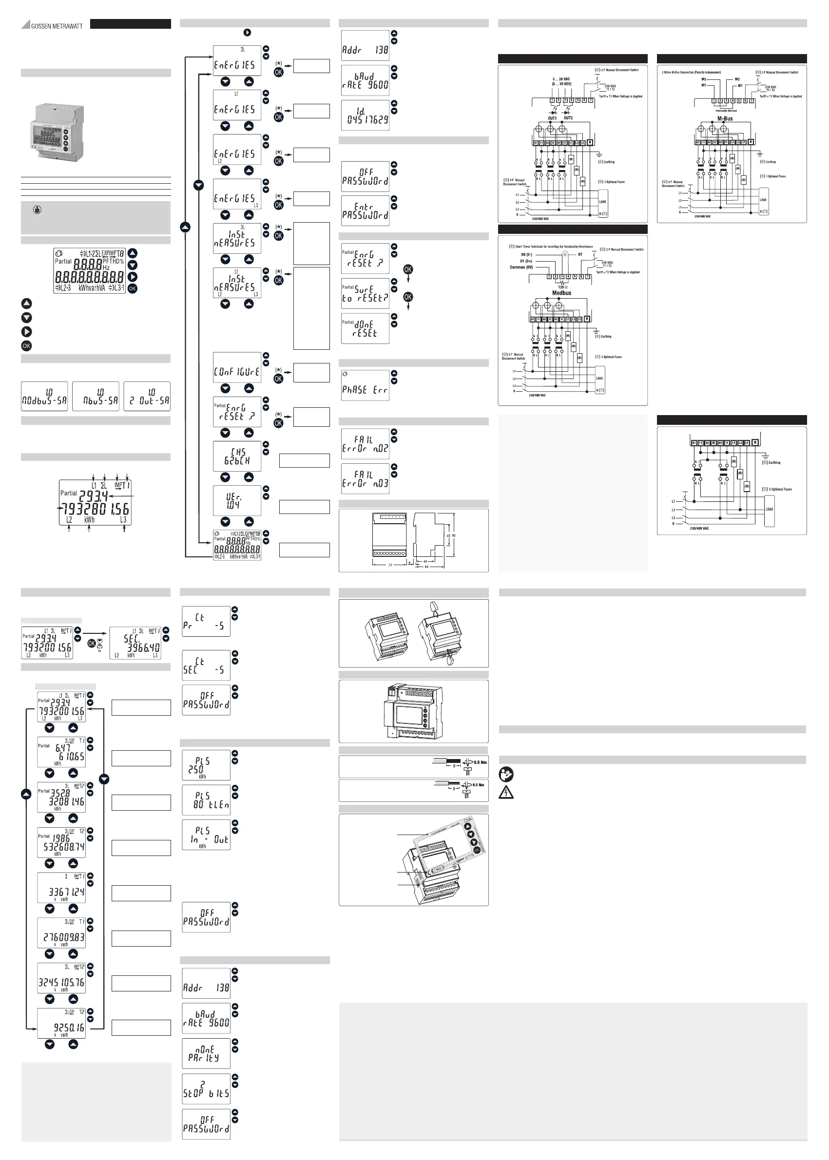
Wiring diagram
• The Energy Meter has OVERVOLTAGE CATEGORY lll (according to IEC 62052-31 that refers to IEC-60664-1 Ed. 2.0:2007), hence its direct connection to the Public Electricity
Grid is not allowed. The Energy Meter is intended for INDOOR installation only (according to EN 50470-1 and IEC 62052-31). The Energy Meter must be installed on a DIN-rail
and inside a cabinet with a protection degree (IP rating) equal to (or better than) IP51. Direct connection of currents inputs to the Energy Meter is NOT ALLOWED: external CTs
insertion with proper insulation level are mandatory.
U289A U289C
U289B
(
①
) The connection of the Neutral Wire to the “N” terminal of the
Power Meter is mandatory.
Its connection to the Load is optional, but, in the case, only 3-phase
measures (Powers and Energies) are meaningful, while measures referred
to L1, L2, and L3 are meaningless.
(
②
) These manual disconnect switches are mandatory for safe installing
operation. Their purpose and location must be easily evident to installation
personnel
(
③
) These fuses are not mandatory, they are recommended to protect the line,
not the device itself. Use 6 A fast (F) or 1 A delayed (T).
(
④
) Earthing of secondary windings of CTs is governed by the laws in force
in the Countries where the device is installed.
Current transformers must not be operated with open terminals since
dangerous high voltages might occur which may result in personal injuries
and property damage; furthermore, in this case the transformers
are exposed to thermal overload.
Alternative wiring diagram, with only 2 external CTs.
To be used only under the following conditions:
• The load is 3 wires (no neutral) and there is no current leakage (l1 - l2 - l3 = 0)
• Only 3-phase measures (∑ Power and Energies) are meaningful.
U289A - U289B - U289C
IIST323-01 - 1/9.22
Main Menu
•
After a long pressure (5 seconds) on OK button in the Main Page, for 120 seconds the
whole set of parameters displayed and transmitted through bus, are referred to
Secondary Side of CTs.
Selecting values at secondary side
Active Imported Energy tariff
T1 with partial register
Three Phase Energies List
Main Page
Main Page
Active Exported Energy tariff
T1 with partial register
Active Imported Energy tariff
T2 with partial register
Active Exported Energy tariff
T2 with partial register
Reactive Imported
Energy tariff T1
Reactive Exported
Energy tariff T1
Reactive Imported
Energy tariff T2
Reactive Exported
Energy tariff T2
Parameters List
External CT related parameters
External CT Primary nominal current
•../5A: configurable between 5 A to 10000 A
with step 5 A
•../1A: configurable between 1 A to 2000 A
with step 1 A
• The default value is 5 A
External CT Secondary nominal current
•../1A or ../5A
• The default value is -5
Parameters in S0 model
Pulses per kWh
• 1 ... 10000 depending on CT ratio.
• The default value is 5000
Pulse time length
• Duration of ON pulse for S0 outputs:
30 to 100 ms.
• The default is 100 ms
S0 ouputs configuration mode
n
In - Out
• S01 proportional to Imported Active Power
• S02 proportional to Exported Active Power
n
Act-React
• S01 proportional to Imported Active Power
• S02 proportional to Imported Reactive Power
n
TAR1-TAR2
• S01 proportional to Imported Active Power
under T1
• S02 proportional to Imported Active Power
under T2
Parameters in models with Modbus on-board
• Modbus Address.
Selectable in the range 1 ... 247.
• The default address is 1.
• Modbus Baud Rate.
Available Baud Rates are:
1200, 2400, 4800, 9600, 19200 and 38400.
• The default baud rate is 19200.
• Modbus Parity.
Available Parity are None, Even and Odd.
• The default Parity is None.
• Modbus Number of Stop Bits (1 or 2).
• The default number of Stop Bits is 1
• Password Enabled/ Disabled
• Password Enabled/ Disabled
• Password Enabled/ Disabled
Main terminals -
Screw driver PZ1
Cable stripping length and max terminal screw torque
Tariff and communication terminals
Screw driver blade 0.8x3.5 mm
Sealable terminal covers
Connectable IR Communication Modules
B
A
A
MID certified
A) Device code and
certification
data indications
B) Safety-sealing between
upper and lower
housing part
◾
Note: Main Page and consequently page sequence could be different, according
to the flowing power and working tariff
Please read this important information!
Intended Use / Use for Intended Purpose
The instrument is a digital multifunctional energy meter certified in accordance with MID. Integrated 4-quadrant measurement permits measurement of
energy import and export.
Thanks to MID certification, acquired data (display) can also be used for the purpose of billing energy costs to third parties.
Via integrated communication interfaces, the values are also forwarded to superordinate management systems. Protection against tampering is provided through
adequate measures (tamper-proof cover).
Safety of the operator, as well as that of the instrument, is only assured when it’s used for its intended purpose
Use for Other than Intended Purpose
Using the instrument for any purposes other than those described in the product documentation is contrary to use for intended purpose.
Liability and Guarantee
Gossen Metrawatt GmbH assumes no liability for property damage, personal injury or consequential damage resulting from improper or incorrect use of the
product, in particular due to failure to observe the product documentation. Furthermore, all guarantee claims are rendered null and void in such cases.
Nor does Gossen Metrawatt GmbH accept any liability for data loss.
3 instrument (U289A) - (U289B) - (U289C)
1 operating instructions
Read and follow these instructions carefully and completely in order to ensure safe and proper use. Keep for future reference.
DANGER
Electric shock due to live components!
Life endangering due to electric arcs!
Touching voltage conducting components is life endangering!
– The installation and any work performed on the instrument may only be carried out by a qualified electrician.
– Observe and comply with all safety regulations which are applicable for your work environment.
– Wear suitable and appropriate personal protective equipment (PPE) whenever working with the instrument.
– During installation, the installation environment must be voltage-free. For that, observe the five safety rules in accordance with DIN VDE 0105-100.
ATTENTION
Faulty installation & incorrect operation
Faulty installation/incorrect operation can damage your instrument/system.
Risk of malfunctions and disruptions
– Comply with the specified technical data and conditions
– Do not install the instrument in potentially explosive atmospheres.
– Do not install the instrument in locations where it may be exposed to direct sunlight.
– Install and operate the instrument only if it and all connection cables and leads are in good working order and damage-free. Inspect the instrument at
regular intervals.
– If the instrument doesn’t function flawlessly, permanently remove it from operation and secure it against inadvertent use.
Applications
Scope of Delivery
Safety Instructions
Produkspesifikasjoner
| Merke: | Gossen Metrawatt |
| Kategori: | energikostnadsmåler |
| Modell: | METRALINE ENERGY U289 ABC |
Trenger du hjelp?
Hvis du trenger hjelp med Gossen Metrawatt METRALINE ENERGY U289 ABC still et spørsmål nedenfor, og andre brukere vil svare deg
energikostnadsmåler Gossen Metrawatt Manualer

2 August 2025
energikostnadsmåler Manualer
Nyeste energikostnadsmåler Manualer
12 September 2025

10 September 2025

9 September 2025

9 September 2025

8 September 2025

8 September 2025
7 September 2025

7 September 2025

7 September 2025
6 September 2025