Growatt ATS-S Bruksanvisning
Growatt
Ikke kategorisert
ATS-S
Les nedenfor 📖 manual på norsk for Growatt ATS-S (2 sider) i kategorien Ikke kategorisert. Denne guiden var nyttig for 9 personer og ble vurdert med 4.8 stjerner i gjennomsnitt av 5 brukere
Side 1/2

1.1.
ATS-S
User Manual
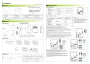
Introduction
The Auto-Transfer Switch Single Phase (ATS-S)controls the switching of the contactors to provide power to the EPS load in both grid-tied
and off-grid conditions. The ATS-S integrates a contactor to provide users with a simple connection. It is used with Growatt Hybrid inverter
and AC coupled inverter (single phase). Configured with ATS-S, when the power outage, ATS-S can automatically switch to Off-Grid state,
it can continue to supply power to the EPS load, the load can continue to run.
2.
The location of ATS in the system-S
8.
4.
General Information - Parts List
3.
Configuration
7.
9.
Model Name
Growatt ATS S-
Grid Normal Voltage
230V 50/60Hz
Grid Max Current
30A
EPS Normal Voltage
230V 50/60Hz
EPS Max Current
30A
Load Normal Voltage
230V 50/60Hz
Load Max Current
30A
Cooling Concept
Natural
Ingress Protection
IP65
Installation
Wall Mountable
-25℃ ~ +50℃
Compatible Model
Operation Ambient
Temperature
Growatt Hybrid inverter and AC
coupled inverter (single phase )
Opening step of ATS-S
Open the ATS-S
As shown above, please put the key into the Keyhole on the ATS-S
right, clockwise rotation of 90°, the lower end of the first lock up
gently move Open, remove the lock at the upper end of the buckle,
then you can open the cover, Step of locking the cover opposite to
the above.
Wiring Connection
There are two type wire connection diagram of ATS , show as below:-S
9.1 total wire diagram
As shown in chart 2.1, the input side ATS-S is connected with
EPS and GRID of SPH/SPA inverter, the output side is connected
with EPS LOAD, and the position in the system is shown in the
circle in the chart 2.1. EPS LOAD default connect with Grid
power, if Grid is lost, EPS LOAD will turn to EPS output of hybrid
inverter.
A
B
C
D
E
F
G
Item ItemItem Name Item Name
Qty Qty
ATS-S ( Auto-Transfer Switch
Single Phase )
User Manual
Anchor Bolt
O -type terminal
1
2
1
10
2 2
3
Key
Cold pressed terminal(large /small)
Contactor control line
Part List Part List
5.
Dimension & Weight
Dimension (L x W x H):312*237*85mm
Weight : 2.38KG
6.
Tool
NO NO
1
2
3
4
5
Description Description
Pipe clamp
Diagonal plier
Screwdriver
Rubber hammer
Driller
1.To leave at least 300mm
space from ATS-S
2.Make the position of 2
holes(282mm) .
3.Drill holes with φ10 drill
Depth: at least 40mm.
a
b
c
1. Wires below are needed before installation(16AWG wire
has been configured in accessory bag).
9.2 wires making
2.Use the diagonal plier to trip 15mm of insulation from one side of
the 10AWG wires(6pcs);
Use the diagonal plier to trip 15mm of insulation from two side of
the 10AWG wires (2pcs,If it is standard 2, you need 3pcs);
Use the diagonal plier to trip 10mm of insulation from two side of
the 12AWG wires(2pcs);
Use the diagonal plier to trip one side of GND wire about
7mm(3pcs).
2
Note:
1.These include 2pcs 10AWG wire (1pcs red, 1pcs black) for
shorting contactor ports 2 and 4, 6 and 8, Its length is about 60cm,
10 AWG N wire (for standard2)length is about 50cm.
Standard 1 is for general using, and standard 2 is for like Australia where Neutral line can't be switched. When connect with ATS S,
please check which standard is suit for you.
-
A
B
C
D
E
F
G
300mm
300mm
300mm
300mm
Produkspesifikasjoner
| Merke: | Growatt |
| Kategori: | Ikke kategorisert |
| Modell: | ATS-S |
| Vekt: | 2380 g |
| Bredde: | 250 mm |
| Dybde: | 85 mm |
| Høyde: | 200 mm |
| AC-inngangsfrekvens: | 50/60 Hz |
| Inngangsspenning (maks.): | 400 V |
| Produktfarge: | Black, White |
| Driftstemperatur (T-T): | -25 - 50 °C |
| Formfaktor: | Vegg-montert |
| Innput-strøm: | 30 A |
| Inngangsspenning (min.): | 230 V |
Trenger du hjelp?
Hvis du trenger hjelp med Growatt ATS-S still et spørsmål nedenfor, og andre brukere vil svare deg
Ikke kategorisert Growatt Manualer

6 September 2025
6 September 2025

6 September 2025

6 September 2025
6 September 2025
6 September 2025

5 September 2025
5 September 2025
5 September 2025

5 September 2025
Ikke kategorisert Manualer
- AirTurn
- Peerless-AV
- Satechi
- G-Technology
- Sescom
- Discover
- Globe
- Syrp
- ButtKicker
- Hirschmann
- Umidigi
- Kino Flo
- Giardino
- LC-Power
- Crock-Pot
Nyeste Ikke kategorisert Manualer

23 Oktober 2025

23 Oktober 2025

23 Oktober 2025

23 Oktober 2025

23 Oktober 2025

23 Oktober 2025

23 Oktober 2025

23 Oktober 2025

23 Oktober 2025

23 Oktober 2025