Klein Tools VDV512-100 Bruksanvisning
Klein Tools
Måleutstyr
VDV512-100
Les nedenfor 📖 manual på norsk for Klein Tools VDV512-100 (9 sider) i kategorien Måleutstyr. Denne guiden var nyttig for 12 personer og ble vurdert med 5.0 stjerner i gjennomsnitt av 6.5 brukere
Side 1/9
GENERAL SPECIFICATIONS
The Klein Tools Coax Explorer
®
2 verifies proper continuity of F-connector coaxial cables and
maps their location. The color-coded push-on remotes allow for up to four cables to be tested
and mapped, displaying cable status via LED indicators (PASS OPEN SHORT, , or ) that also
identify the cable/remote location.
• Environment: Indoor
• Operating Altitude: 10000 ft. (3000 m) maximum
• Operating Temperature: ° ° ° °32 to 122 F (0 to 50 C)
• Storage Temp: ° ° ° °-4 to 140 F (-20 to 60 C)
• Relative Humidity: 10% to 90% non-condensing
• Dimensions (including remote holder): 5.7" x 2.3" x 1.1" (145 x 32 x 29 mm)
• Weight (including batteries): 4.8 oz. (136 g)
Specifications subject to change.
TESTING/MAPPING CABLES
NOTE: Not for use on powered circuits or outlets.
1. Connect a test remote
1
,
2
,
3
or
4
to one end of the cable or outlet to be
tested. If necessary, use the included F-adapter
9
to connect the test remote to the
cable. If mapping, install remaining remotes to additional locations.
2.
Connect the opposite end of the cable or outlet to be tested to the F-connector
5
on
the Coax Explorer
®
2.
3.
Press and hold the button TEST
10
. If the cable is wired correctly, one of the four PASS
LEDs
11
will light, also indicating the cable/remote location. If there is a problem with
the cable, one of the FAULT OPEN LEDs (
12
or SHORT
13
) will light.
4.
Repeat steps 2 and 3 to test/map additional cables.
TESTING AN UNINSTALLED CABLE
1. Using the included F-adapter
9
, connect a test remote
1
to one end of the cable to be
tested.
2.
Connect the opposite end of the cable to be tested to the F-connector
5
on the Coax
Explorer
®
2.
3.
Press and hold the button TEST
10
. If the cable is wired correctly, the corresponding
PASS LED
11
will light. If there is a problem with the cable, one of the FAULT LEDs
( OPEN
12
or SHORT
13
) will light.
REMOTE HOLDER/STORAGE
The test remotes conveniently snap into the remote holder
8
for storage. To store the
included F-adapter
9
, push two remotes onto the adapter before snapping the remotes into
the holder.
The remote holder snaps onto the body of the Coax Explorer
®
2 and may be removed if
desired. Hold the tester in one hand and apply slight downward pressure to one side of the
remote holder with the other hand to release it from the tester. To reattach, align the holder
with the tester body and snap back into place.
BATTERY REPLACEMENT (FIG. 1)
When the TEST button is pressed and no LEDs light, the batteries must be replaced.
1. Unscrew the battery cap
6
.
2. Remove and recycle the two spent AAA batteries
7
.
3.
Install two new AAA batteries, with the positive (+) side facing into the tester as shown.
4. .Screw battery cap tightly back into place
STORAGE
Remove the batteries when the tester is not in use for a prolonged period of time. Do not expose
to high temperatures or humidity. After a period of storage in extreme conditions exceeding the
limits mentioned in the GENERAL SPECIFICATIONS section, allow the tester to return to normal
operating conditions before using.
FCC AND IC COMPLIANCE
See this product’s page at for FCC compliance information.www.kleintools.com
Canada ICES-003 (B) / NMB-003 (B)
WARRANTY
www.kleintools.com/warranty
DISPOSAL / RECYCLE
Do not place equipment and its accessories in the trash. Items must be properly
disposed of in accordance with local regulations. Please see
www.epa.gov/recycle for additional information.
CUSTOMER SERVICE
KLEIN TOOLS, INC.
450 Bond Street, Lincolnshire, IL 60069 1-800-553-4676
customerservice@kleintools.com www.kleintools.com
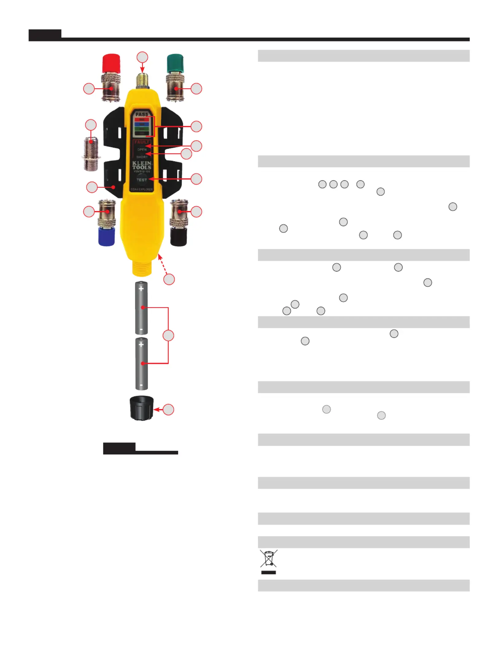
FIG. 1
5
8
1 3
10
12
13
11
4
9
2
14
7
6
ENGLISH
ENGLISH
1.
Test Remote #1 (Red)
2.
Test Remote #2 (Blue)
3.
Test Remote #3 (Green)
4.
Test Remote #4 (Black)
5.
F-Connector
6.
Battery Cap
7.
2x AAA Batteries
(included)
8.
Remote Holder
9.
F-Adapter
10.
TEST Button
11.
PASS LEDs
12.
OPEN Fault LED
13.
SHORT Fault LED
14.
Pocket Clip (Back)
NOTE: There are no
user-serviceable
parts inside tester.
VDV512-101 Instructions
BASED ON 1330430 Rev. 11/21 E
Produkspesifikasjoner
| Merke: | Klein Tools |
| Kategori: | Måleutstyr |
| Modell: | VDV512-100 |
| Vekt: | 85 g |
| Bredde: | 32 mm |
| Dybde: | 146 mm |
| Høyde: | 25 mm |
| Batteritype: | AAA |
| Antall støttede batterier: | 2 |
| Støttede kontakter: | BNC, RJ-11 |
Trenger du hjelp?
Hvis du trenger hjelp med Klein Tools VDV512-100 still et spørsmål nedenfor, og andre brukere vil svare deg
Måleutstyr Klein Tools Manualer
18 Februar 2025

21 Januar 2025

21 Januar 2025

14 Januar 2025

14 Januar 2025

12 Januar 2025

11 Januar 2025

2 Januar 2025

29 Desember 2024

21 Oktober 2024
Måleutstyr Manualer
- Metrix
- Grundfos
- Kyoritsu
- Chauvin Arnoux
- Toolland
- Wachendorff
- Mitutoyo
- Einhell
- Ermenrich
- Testec
- Techno Line
- Basetech
- Panasonic
- Benning
- Aim TTi
Nyeste Måleutstyr Manualer

3 April 2025

3 April 2025

3 April 2025

3 April 2025

3 April 2025

3 April 2025

3 April 2025

3 April 2025

3 April 2025

3 April 2025