Little Giant TP 553674 Bruksanvisning
Little Giant
pumpe
TP 553674
Les nedenfor 📖 manual på norsk for Little Giant TP 553674 (8 sider) i kategorien pumpe. Denne guiden var nyttig for 16 personer og ble vurdert med 5.0 stjerner i gjennomsnitt av 8.5 brukere
Side 1/8

1
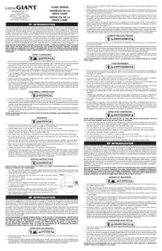
Modelos
ENGLISH
EN
This instruction sheet provides you with the information required to safely own
and operate your product. Retain these instructions for future reference.
The product you have purchased is of the highest quality workmanship and
material, and has been engineered to give you long and reliable service. This
product has been carefully tested, inspected, and packaged to ensure safe
delivery and operation. Please examine your item(s) carefully to ensure that no
damage occurred during shipment. If damage has occurred, please contact the
place of purchase. They will assist you in replacement or repair, if required.
We, Franklin Electric, declare that our pumps TPR, TPT & TPS with pump type
and serial number as shown on the nameplate are constructed in accordance
with Directives 2006/95/EC and 89/336/EEC and assume full responsibility for
conformity with the standards laid down therein.
Your Little Giant peristaltic condensate pump is designed as a fully automatic
condensate removal system for the water dripping off an air conditioner
evaporator coil. The pump is not for contiuous use applications. The pump you
have purchased is a small but powerful drain pump for the positive displacement
of condensate from fan coils and air conditioners. The design of this pump allows
the air handler to be located away from gravity water drains since the condensate
can be pumped to a common drain a distance away. The peristaltic pump is
designed to remove condensation from fan coil, wall-mount, ceiling and cassette
air conditioning equipment.
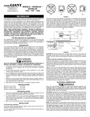
1. This pump is not to be used to pump flammable or explosive fluids such
as gasoline, fuel oil, kerosene, etc. Do not use this pump in explosive
atmospheres.
2. Do not handle pump with wet hands or when standing on a wet, damp
surface or when standing in water.
3. In any installation where property damage and/or personal injury might result
from an inoperative or leaking pump due to power outages, discharge line
blockage, or any other reason, a backup system(s) and/or alarm should be
used.
4. Support pump and piping when assembling and when installed. Failure to
do so may cause piping to break, pump to fail, motor bearing failures, etc; or
may cause the pump to malfunction.
5. Place pump in an area where there is no danger of ingress of water.
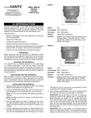
Maximum suction head: 2m (6.5 ft)
Maximum delivery head: 14m (49 ft)
Maximum ambient temperature: 50°C (122°)
1. Check the pump label for proper voltage and frequency required. Do not
connect to voltage and frequency other than that shown.
2. It is recommended to use ¼” I.D. or 6 mm I.D. tubing for both the inlet and
outlet. Inlet tubing is connected to the inlet fitting identified by an upward
arrow. Outlet or discharge tubing is connected to the outlet fitting identified
by a downward arrow.
3. Make sure the transparent cover is closed before operating.
The pump can be mounted adjacent, below or above (but not more than 2m
above) the condensate water source.
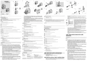
For best results, mount the pump with the hose connections facing down as
shown in Figure 1B.
A B C D
The pump may also be positioned on any side, but not placed rotor downward
(Figure 1C) or upward (Figure 1A). Connect 6.0mm or 1/4” tubing (not provided)
to the pump intake indicated by the arrow pointing upward on the transparent
cover. Position the other end of the intake tube in the drip tray drain hose and
seal it accordingly or place the intake tube in the drip tray (Figure 2). Be careful
not to twist, kink, or collapse the tubing. Run a length of 6.0mm or ¼” tubing (not
provided) from the discharge of the pump to a gravity drain. Refer to Figure 2 for
maximum vertical and horizontal discharge capabilities.
"Y r v r"
TPT
16 ft (5 m)
max
98 ft (30 m)
max
46 ft (14 m)
max
Lt. blue
Brown
Alternative position for inlet tube
To pump
Internal
drain tray
Inlet tube fixed
inside tray
outlet with
sealant
Ceiling
Red end: room air
sensor, intake air
Blue end: cold air
sensor, intake air
Coil
Block off unit drain
Internal drain tray
Wall or below ceiling A/C unit
6.5 ft (2 m) max
Be certain that there are no sharp bends or kinks in the suction and
discharge tubing. Keep all tubing and cables clear of moving parts in the air
handler. If using Ty-raps to secure tubing, be certain the Ty-rap does not collapse
tubing.
Locate the float reservoir in a suitable position below the bottom level of the drip
tray of the air conditioner. Be certain that the reservoir is within (+/-) 15 degrees
of being level. Optimum performance is achieved when the reservoir is level. If the
reservoir is not mounted properly, the float mechanism may not function properly
and may overflow.
Attach the 13mm (1/2”) tube (provided) to the reservoir intake and the drip tray
outlet or drain hose. Be certain to support the reservoir when attaching tubing
and make sure the tubing is not twisted, kinked or collapsed when reservoir is
in place. Connect the long 4 x 6 mm (5/32”) tubing (provided)to the discharge
of the reservoir marked “PUMP”. Connect the other end of the 4 x 6 mm (5/32”)
tubing to the provided 4 x 6 mm adapter. Use a short piece of 6 mm or ¼” tubing
(not provided) to connect the 4 x 6 mm adapter to the pump inlet fitting identified
by an upward arrow. Connect the short 4 x 6 mm (5/32”) tubing (provided) to
the outlet of the reservoir marked “VENT”. The free end of the tubing must be
directed upward above the drip tray to prevent overflow. Be certain the tubing is
not twisted, kinked or collapsed when installed.
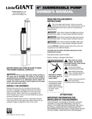
SHUT OFF ELECTRICAL POWER AT FUSE BOX BEFORE MAKING ANY
CONNECTIONS. ALL WIRING MUST COMPLY WITH LOCAL CODES. CHECK
THE PUMP LABEL FOR PROPER VOLTAGE REQUIRED. DO NOT CONNECT TO
VOLTAGE OTHER THAN THAT SHOWN.
(compressor or cooling signal) - Connect the brown wire to the main
phase (line), the blue wire to the neutral phase (common). The pump must not
be connected to a switched line. Electricity should always be provided on this
line. Connect the orange wire to the compressor or cooling signal (Figure 3).
When the compressor engages, a 230V supply voltage will be sent to start the
pump. When the compressor stops operating, the pump will not stop. The pump
is programmed to continue operating for another 5 minutes to collect any residual
condensate before stopping.
: The compressor or cooling signal neutral phase (common) needs to be
the same neutral phase (common) that is used to supply power to the controller.
(temperature signal) FOR PROPER PUMP OPERATION, PLEASE
FOLLOW THESE INSTRUCTIONS: Connect the brown wire to the main phase
(line) and the blue wire to the neutral phase (common) (Figure 2). Make sure
power is off when connecting the temperature sensor to the pump. Connect the
sensor cable to the pump by connecting the 4-prong plug to the corresponding
Oklahoma City, OK
www.LittleGiantPump.com
customerservice@lgpc.com
Produkspesifikasjoner
| Merke: | Little Giant |
| Kategori: | pumpe |
| Modell: | TP 553674 |
Trenger du hjelp?
Hvis du trenger hjelp med Little Giant TP 553674 still et spørsmål nedenfor, og andre brukere vil svare deg
pumpe Little Giant Manualer
27 August 2025
26 August 2025
26 August 2025
26 August 2025
pumpe Manualer
- Draper
- Eheim
- Hayward
- Ryobi
- Zipper
- Biltema
- Comet
- Parkside
- Karcher
- SKS
- JANDY
- Lezyne
- Sauermann
- Einhell
- Liberty Pumps
Nyeste pumpe Manualer
6 Oktober 2025
6 Oktober 2025
6 Oktober 2025
6 Oktober 2025
6 Oktober 2025
5 Oktober 2025

5 Oktober 2025
5 Oktober 2025
5 Oktober 2025

5 Oktober 2025