Milwaukee 48-22-8546 Bruksanvisning
Milwaukee
Ikke kategorisert
48-22-8546
Les nedenfor 📖 manual på norsk for Milwaukee 48-22-8546 (11 sider) i kategorien Ikke kategorisert. Denne guiden var nyttig for 13 personer og ble vurdert med 4.8 stjerner i gjennomsnitt av 7 brukere
Side 1/11
(2)
(4)
(4)
(5)
(6)
M6
(7)
2PCS
(7)
(8)
III
Back
M4*12
(1)
4PCS
M6*16
(4)
8PCS
M8*12
(5)
16PCS
M6*12
(3)
2PCS
M4*16
(2)
12PCS
19×8.5×2
(6)
16PCS
M6*8
(8)
2PCS
Cat. No. / No de cat.
48-22-8541, 48-22-8542
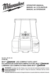
OPERATOR'S MANUAL
MANUEL de L'UTILISATEUR
MANUAL del OPERADOR
WARNING To reduce the risk of injury, user must read and understand operator's manual.
AVERTISSEMENT An de réduire le risque de blessures, l'utilisateur doit lire et bien
comprendre le manuel.
ADVERTENCIA Para reducir el riesgo de lesiones, el usuario debe leer y entender el manual.
Este manual se aplica a los modelos anteriores (puede venderse por separado)
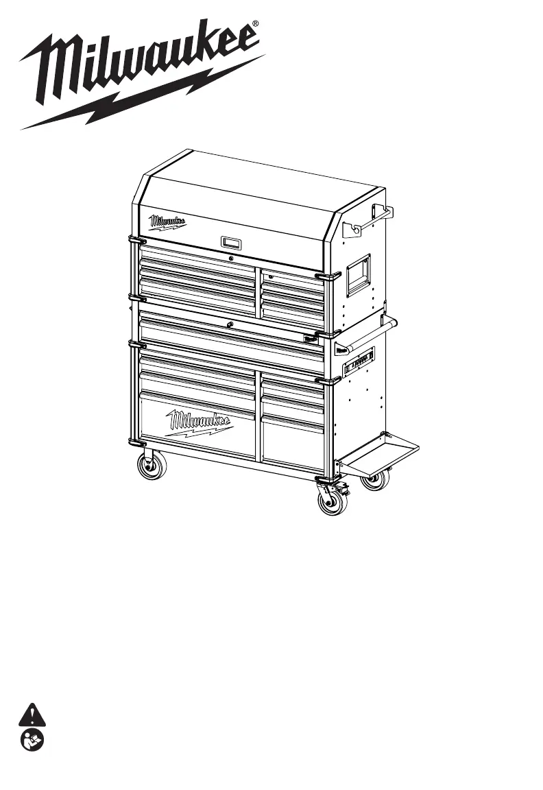
46" HIGH CAPACITY STEEL STORAGE CHEST &
46" HIGH CAPACITY STEEL STORAGE CABINET
COFFRE DE RANGEMENT EN ACIER GRANDE CAPACITÉ DE
1,16 M (46") ET CABINET DE RANGEMENT EN ACIER GRANDE
CAPACITÉ DE 1,16 M (46")
CAJA DE ALMACENAMIENTO DE ACERO DE GRAN CAPACIDAD
DE 1,16 M (46") Y GABINETE DE ALMACENAMIENTO DE ACERO
DE GRAN CAPACIDAD DE 1,16 M (46")
Produkspesifikasjoner
| Merke: | Milwaukee |
| Kategori: | Ikke kategorisert |
| Modell: | 48-22-8546 |
Trenger du hjelp?
Hvis du trenger hjelp med Milwaukee 48-22-8546 still et spørsmål nedenfor, og andre brukere vil svare deg
Ikke kategorisert Milwaukee Manualer
19 September 2025
19 September 2025
16 August 2025
15 August 2025
15 August 2025
15 August 2025
15 August 2025
15 August 2025
15 August 2025
14 August 2025
Ikke kategorisert Manualer
- Fiamma
- GW Instek
- Nous
- Vestil
- Xplora
- Wet Sounds
- E-ast
- Bresser
- Marshall Electronics
- Media-tech
- LAS
- Blaupunkt
- Eufy
- DCS
- Ferrofish
Nyeste Ikke kategorisert Manualer

23 Oktober 2025

23 Oktober 2025

23 Oktober 2025

23 Oktober 2025

23 Oktober 2025

23 Oktober 2025

23 Oktober 2025

23 Oktober 2025

23 Oktober 2025

23 Oktober 2025