NAKS SF7 Bruksanvisning
NAKS
eksoshette
SF7
Les nedenfor 📖 manual på norsk for NAKS SF7 (7 sider) i kategorien eksoshette. Denne guiden var nyttig for 7 personer og ble vurdert med 4.9 stjerner i gjennomsnitt av 4 brukere
Side 1/7
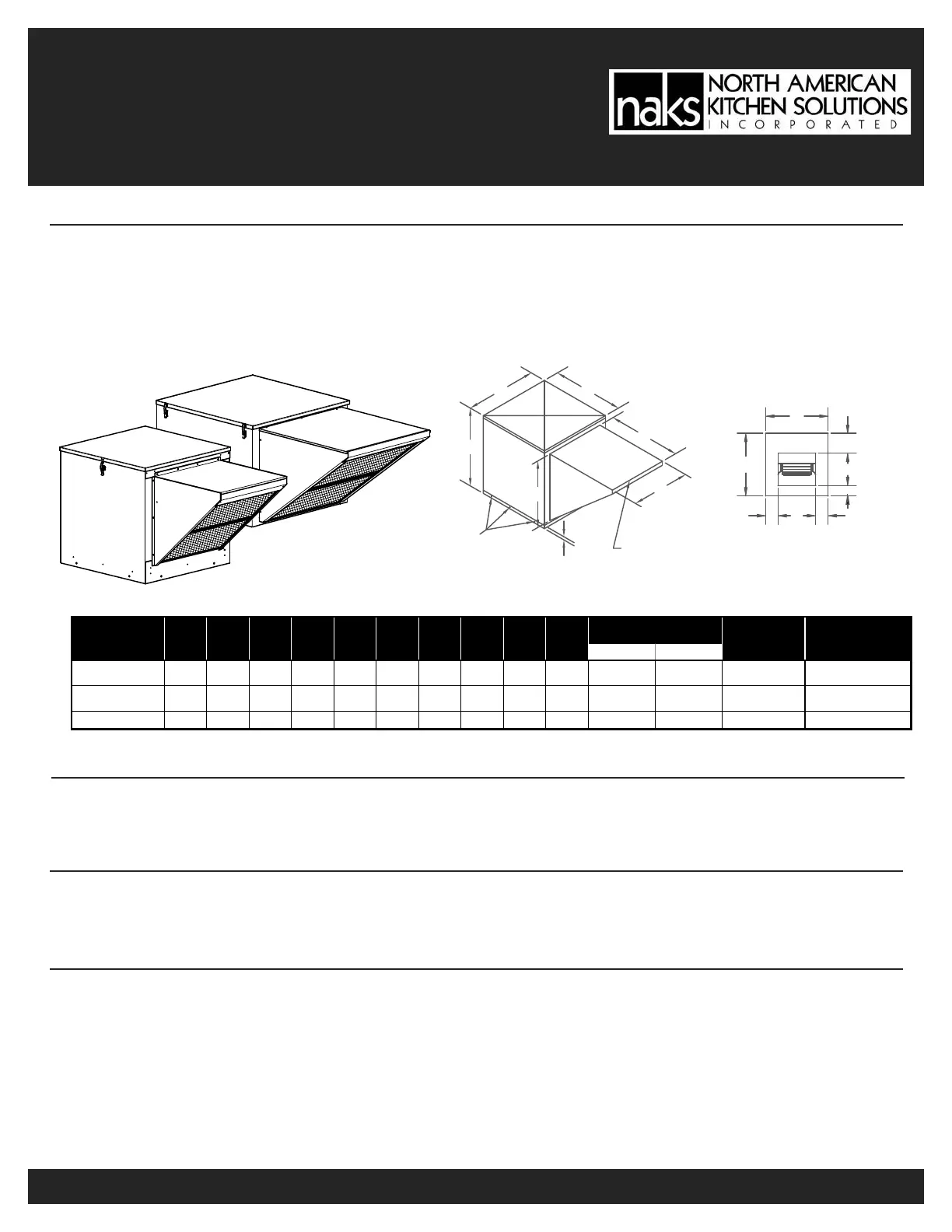
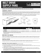
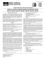
BELT DRIVE
SUPPLY FANS
OPERATION INSTRUCTIONS AND PARTS MANUAL
MODELS: SF5, SF5-3PH, SF7, SF7-3PH, SF8, SF8-3PH, SF9, SF9-3PH, SF10, SF10-3PH
GENERAL SAFETY
Rotating parts, (pulleys, shafts and belts) on fans should not be exposed. Where these components are not protected by ductwork, cabinets
or covers, appropriate guards should be employed to restrict exposure to rotating parts. Access doors should not be opened with the fan
operating to avoid foreign objects being drawn into the system. On initial start-up, a careful inspection should be carried out to ensure no
foreign material is present which could become airborne in the system.
Read installation and operation instructions carefully before attempting to install, operate or service NAKS SF Series Blowers. Failure to
comply with instructions could result in personal injury and/or property damage. Retain instructions for future reference.
BEFORE YOU BEGIN
Inspect unit for damage, report any shipping damage to carrier. Check all fasteners, re-tighten as required. Rotate the blower wheel by
hand to ensure free rotation. If rubbing occurs, loosen the set screw(s), re-position the wheel to the shaft center, re-tighten set screws.
INSTALLATION
Remove hood and filters from inside the cabinet. Caulk top of curb before setting unit in place. (Curb must be smaller than unit “A”
dimension). Secure unit to curb through holes located around the bottom of the unit. Tighten wheel set screw.
A
A
F
E
F
G
D
H
BOTTOM VIEW
SIZE QUANTITY
SF5 / SF5-3PH
SF7 / SF7-3PH
22" 24" 11 7/8" 13 1/4" 4 7/16" 3 1/4" 6 7/8" 16" 18 1/8" 19 7/8" 16" x 25" x 1" 1 21 7/8" x 21 7/8" TBA
SF8 / SF8-3PH
SF9 / SF9-3PH
32" 32" 13 3/4" 15 7/8" 8 1/16" 4 1/4" 14" 25" 24 5/8" 25" 16" x 25" x 1" 2 31 7/8" x 31 7/8" TBA
SF10 / SF10-3PH 32" 32" 16 1/8" 18 7/8" 6 9/16" 3 7/8" 12 7/8" 25" 24 5/8" 25" 16" x 25" x 1" 2 31 7/8" x 31 7/8" TBA
UNIT WEIGHT (LBS)
(without motors & drives)
HLMZ
FILTERS
*INSIDE
CABINET
ABDEFGMODEL
2017 Page 1 of 4
AA
B
Z
L
REMOVE CAP FOR
FILTER ACCESS
2"
Ø5/16" HOLES
FOR FASTENING
TO CURB
M
MOTOR, PULLEYS & BELTS (See Table next page)
1. Mount the blower pulley on the blower shaft and tighten the set screw securely on the key of the shaft.
2. Mount the motor pulley on the motor shaft. Leave some clearance between the pulley and the motor end bell. Tighten the set screws
on the key of the motor shaft.
3. Install the motor on the motor platform using the hardware provided.
4. With the platform in its minimum position, install the V-belt within the pulley grooves. Position the motor on the motor platform to
ensure proper pulley alignment (see Figure 1) and secure to the motor platform. (A straight edge across the face of the driven pulley
should be parallel to the belt once proper alignment has been achieved).
Note: Adjustments in the variable speed pulley require pulley re-alignment.
*Curb size to be smaller than inside cabinet to allow for flashing and roofing.
**Includes filter section
Produkspesifikasjoner
| Merke: | NAKS |
| Kategori: | eksoshette |
| Modell: | SF7 |
Trenger du hjelp?
Hvis du trenger hjelp med NAKS SF7 still et spørsmål nedenfor, og andre brukere vil svare deg
eksoshette NAKS Manualer

22 September 2025
22 September 2025

22 September 2025
21 September 2025

21 September 2025
21 September 2025
21 September 2025

21 September 2025

21 September 2025

21 September 2025
eksoshette Manualer
- Viking
- Vollrath
- Faber
- Vivax
- Fagor
- Defy
- Blomberg
- Constructa
- Euro Appliances
- Broan
- Master Kitchen
- Pelgrim
- Omega
- Canarm
- Cylinda
Nyeste eksoshette Manualer

21 Oktober 2025

21 Oktober 2025
20 Oktober 2025

20 Oktober 2025

18 Oktober 2025

18 Oktober 2025
14 Oktober 2025

12 Oktober 2025
11 Oktober 2025

11 Oktober 2025