PCE Instruments PCE-BPD-U-41D Bruksanvisning
PCE Instruments
måleinstrument
PCE-BPD-U-41D
Les nedenfor 📖 manual på norsk for PCE Instruments PCE-BPD-U-41D (25 sider) i kategorien måleinstrument. Denne guiden var nyttig for 7 personer og ble vurdert med 4.4 stjerner i gjennomsnitt av 4 brukere
Side 1/25
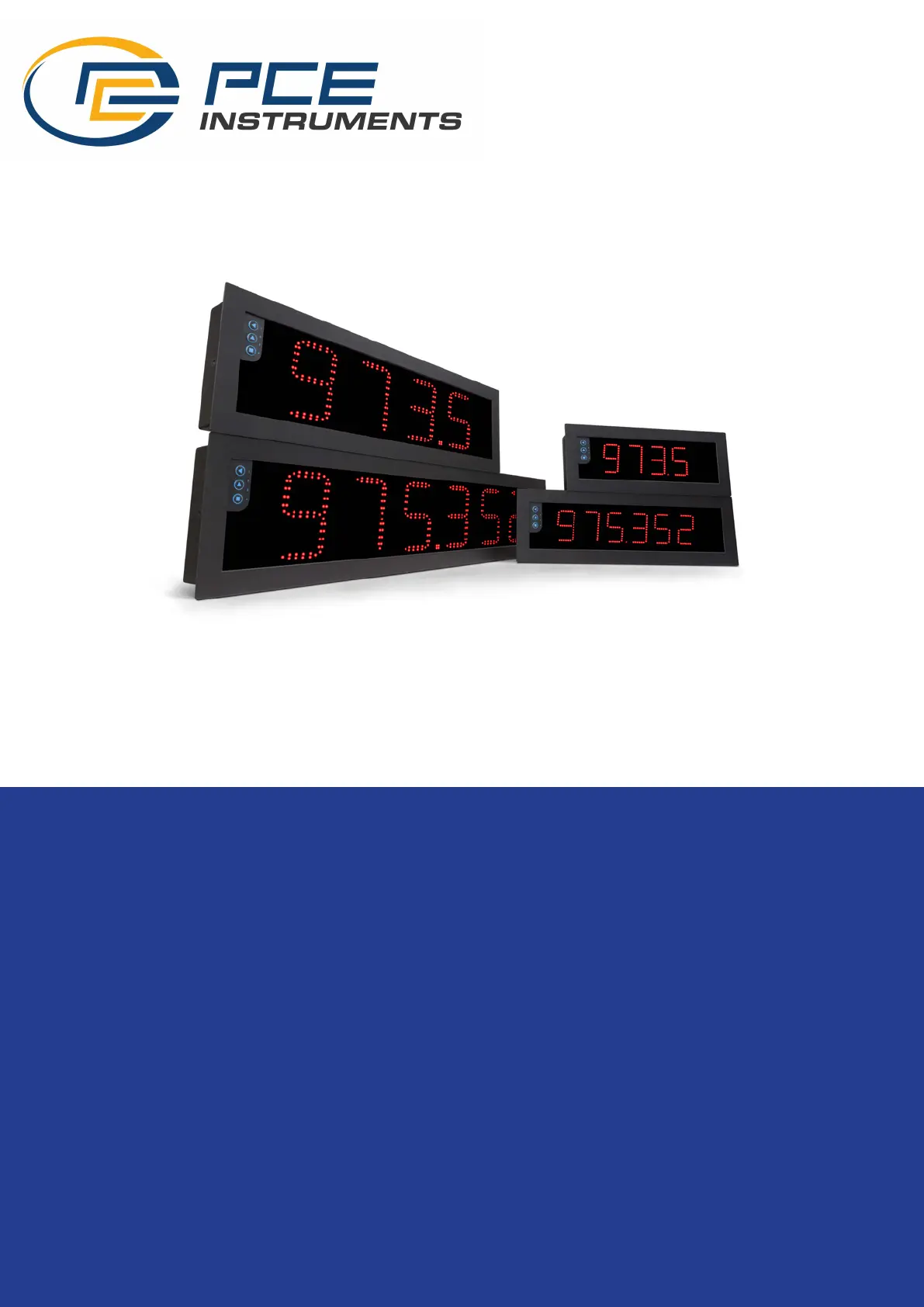
Process meters
Big panel displays for process signals in mA and Vdc. Dierent formats available with 60 mm and 100
mm digit height, 4 and 6 digits, in red color. Sturdy metal housing, with full IP65 protecon, designed for
panel, wall or hanging mount. Versale and congurable, provides excitaon voltage to power up the
transducer, segment linearizaon, fast access to alarm setpoints, ‘on power up’ funcon, ‘measure’ func
-
on’ and 5 congurable brightness levels. Universal AC and DC power. Accepts up to 3 output and control
op
ons (relays, analog retransmission, Modbus RTU, transistor outputs, RS-485 ASCII, ...). Conguraon
from frontal keypad or remote keypad.
BIG PANEL DISPLAYS
5532r02
User’s Manual
PCE-BPD-U
www.pce-instruments.com
Produkspesifikasjoner
| Merke: | PCE Instruments |
| Kategori: | måleinstrument |
| Modell: | PCE-BPD-U-41D |
Trenger du hjelp?
Hvis du trenger hjelp med PCE Instruments PCE-BPD-U-41D still et spørsmål nedenfor, og andre brukere vil svare deg
måleinstrument PCE Instruments Manualer
3 Oktober 2025
2 Oktober 2025
2 Oktober 2025
1 Oktober 2025
12 September 2025
12 September 2025

3 September 2025

3 September 2025
26 August 2025
26 August 2025
måleinstrument Manualer
- Gossen Metrawatt
- GW Instek
- Fluke
- Ebro
- Tripp Lite
- Sauter
- Bosch
- Dasqua
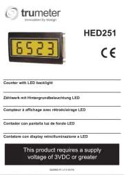
- Trumeter
- Mitsubishi
- Grundfos
- Bender
- DataVideo
- Kimo
- Sanwa
Nyeste måleinstrument Manualer
21 Oktober 2025
21 Oktober 2025
20 Oktober 2025
19 Oktober 2025
16 Oktober 2025
16 Oktober 2025

15 Oktober 2025
15 Oktober 2025
15 Oktober 2025
13 Oktober 2025