Pulsar AWT468 Bruksanvisning

Les nedenfor 📖 manual på norsk for Pulsar AWT468 (4 sider) i kategorien Ikke kategorisert. Denne guiden var nyttig for 2 personer og ble vurdert med 4.5 stjerner i gjennomsnitt av 2 brukere

Side 1/4
INSTRUKCJA MONTAŻU/ASSEMBLY INSTRUCTIONS
POLSKI/ENGLISH
Kod / code: AWT468, AWT682, AWT8161820, AWT8172430
Nazwa/ Name: TRZ 40/U1/U2, TRZ 60/U1/U2, TRZ 80/U1/U2/U3*
IU-TRAFO TRZ
Wydanie: 12 z dnia 06.06.2024
Zastępuje wydanie: 11 z dnia 11.04.2019
* -/U1/U2,U3= napięcie wtórne
* -/U1/U2,U3=secondary voltage
PL
1. Opis techniczny.
1.1. Przeznaczenie.
Transformator AWT xxx przeznaczony jest do zasilania urządzeń wymagających napięcia AC: U1, U2 lub U3.
Moc odbiorników dołączonych do zacisków transformatora nie może przekroczyć jego mocy znamionowej.
W celu zachowania wymaganej klasy szczelności (IP43) transformator należy montować w pozycji
pionowej zgodnie z rysunkiem rys.1 /rys.2.
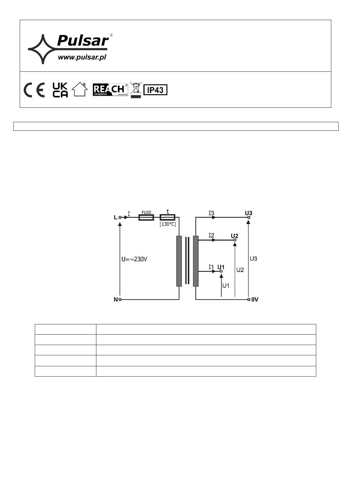
1.2. Schemat elektryczny.
1.3. Opis złącz i elementów transformatora.
Element
Opis
L-N
złącze uzwojenia pierwotnego, zasilania ~230 V
COM-U1-U2-U3
złącze uzwojenia wtórnego, napięcia wyjściowe
FUSE
bezpiecznik topikowy w obwodzie zasilania (~230 V)
t
bezpiecznik termiczny 130
°
C (niepowracalny)
2. Montaż.
Transformator przeznaczony jest do montażu przez wykwalifikowanego instalatora, posiadającego odpowiednie
(wymagane i konieczne dla danego kraju) zezwolenia i uprawnienia do przyłączania (ingerencji) w instalacje 230 V oraz
instalacje niskonapięciowe.
Ponieważ transformator zaprojektowany jest do pracy ciągłej nie posiada wyłącznika zasilania, dlatego należy
zapewnić właściwą ochronę przeciążeniową w obwodzie zasilającym. Należy także poinformować użytkownika o sposobie
odłączenia zasilacza od napięcia sieciowego (najczęściej poprzez wydzielenie i oznaczenie odpowiedniego bezpiecznika w
skrzynce bezpiecznikowej). Instalacja elektryczna powinna być wykonana według obowiązujących norm i przepisów.
W celu zachowania wymaganej klasy szczelności (IP43) transformator należy montować w pozycji pionowej
zgodnie z rysunkiem rys.1 /rys.2.
2
Transformator powinien być montowany w pomieszczeniach zamkniętych o normalnej wilgotności
powietrza (RH=90% maks. bez kondensacji) i temperaturze z zakresu -10°C do +40°C. Należy zapewnić
swobodny przepływ powietrza wokół transformatora.
Transformator należy montować w urządzeniu końcowym (szafy sterownicze, kasety, obudowy)
którego obudowa zapewnia ochronę przed porażeniem prądem elektrycznym.
Przed przystąpieniem do instalacji należy upewnić się, że napięcie w obwodzie zasilającym
230V AC jest odłączone.
1. Zamontować transformator w wybranym miejscu: na płaskiej powierzchni lub na szynie DIN z użyciem
adapterów (AWO466 dla TRZ40VA ÷ TRZ60VA lub AWO467 dla TRZ50VA ÷ TRZ80VA) oraz doprowadzić
przewody połączeniowe.
2. Przewody zasilania ~230 V podłączyć do zacisków 230 V L-N transformatora.
3. Podłączyć wyjście transformatora do urządzenia.
Uwagi: podłączyć wymagane napięcie U1 lub U2 lub U3 dla danego urządzenia zwracając uwagę aby maksymalna
moc odbiorników nie przekraczała dopuszczalnej mocy transformatora.
4. Wykonać opcjonalnie pozostałe połączenia wymagane dla danego typu urządzenia/systemu.
Uwagi: zgodnie z wymaganiami i zaleceniami producenta.
5. Wykonać uruchomienie (załączenie zasilania ~230 V), regulacje lub konfiguracje: zgodnie z procedurą producenta
systemu, urządzenia.
EN
1. General description.
1.1. Destination.
The AWT xxx, transformer is designed for the supply of equipment requiring the AC voltage: U1 or U2 or U3.
The power of devices connected to the terminals must not exceed the power of the transformer.
To maintain the required degree of protection class (IP43), transformer must be installed in a vertical
position as shown in Fig.1 / Fig.2.
1.2. Electrical diagram.
1.3. Description of elements and power supply connectors.
Element
Description
L-N
Primary circuit connector, ~230 V supply connector
COM-U1-U2-U3
Secondary circuit connector, output voltage connector
F
Fuse in the power supply circuit (~230 V)
t
Non-ressetable fuse 130°C
3
2. Installation.
The safety transformer must be installed by a qualified installer, holding the relevant certificates, required and
necessary in the particular country for connecting (interfering with) the 230 V systems and low-voltage installations.
Because the transformer is designed for the continuous operation and is not equipped with ON/OFF switch, the
power supply line should have the appropriate overload protection. The user should be informed how to disconnect the
transformers from the mains (usually be means of the separate fuse in the fuse-box). The power supply installation
should conform to the applicable standards and law.
To maintain the required degree of protection class (IP43), transformer must be installed in a vertical position as
shown in Fig.1 / Fig.2.
The transformer should be installed indoors (controls cabinets, casings), where air humidity is
normal (RH=90% max. without condensation) and temperature in the range of -10°C to +40°C.
Provide sufficient airflow around the transformer for convectional cooling.
Caution!
Prior to entering installation it is necessary to make sure if the voltage
in the 230 V circuit is disconnected.
1. Install the transformer at the selected place: plain surface or on the DIN rail with the adaptors (AWO466 for
TRZ40VA ÷ TRZ60VA or AWO467 for TRZ50VA ÷ TRZ80VA) and evacuate connection wires.
2. Supply conductors ~230 V should be connected to 230 V L-N terminals of the transformer.
3. Connect the output transformer to a device, using installed cables
Remarks: Connect required voltage U1 or U2 or U3 (secondary voltage) for the correct device. The power of
connected devices must not exceed the power of the transformer.
4. If necessary, make other connections required for the correct type of system / device.
Remarks: consistent with requirements and recommendation of the producer.
5. Start the system (switch on ~230 V), adjust or configure: according to procedure of the producer’s system.
3. Parametry techniczne / Technical data.
Tab 1.
PARAMETRY
TECHNICZNE
TECHNICAL
DATA
Napięcie zasilania
Power supply voltage
~230 V; 50 Hz
(-15%/+10%)
Napięcie wyjściowe
U1/U2/U3
Power supply voltage
U1/U2/U3
Tab. 2
Prąd wyjściowy nominalny
I1/I2/I3
Nominal output current
I1/I2/I3
Tab. 2
Zabezpieczenie przeciwzwarciowe i
przeciążeniowe
Short circuit and overload protection
Bezpiecznik / Fuse
Tab. 2
Zabezpieczenie termiczne
Thermal protection
130°C (niepowracalne)
Non-ressetable fuse 130
o
C
Złącza podłączeniowe
Terminal block
AWG24÷12 2,5mm
2
Obudowa
Casing
PC/ABS
UL94-V0
Klasa szczelności IP
IP degree
IP 43
Temperatura pracy /
Klasa cieplna
Operating temperature /
Heat class
-10ºC÷40ºC
Ta 40B
Wilgotność względna RH – max.
Relative humidity RH max.
90 [%]
Wymiary (szer x wys x głeb)
TRZ 40/U1/U2÷ TRZ 60/U1/U2
Dimensions (W x H x D )
TRZ 40/U1/U2÷ TRZ 60/U1/U2
75 x 124 x 65 [mm] (+/-2)
Rys./Fig. 1
Wymiary (szer x wys x głeb)
TRZ 50/U1/U2/U3÷ TRZ 80/U1/U2/U3
Dimensions (W x H x D )
TRZ 50/U1/U2/U3÷ TRZ 80/U1/U2/U3
95 x 136 x 76 [mm] (+/-2)
Rys./Fig. 2
Waga netto
TRZ 40/U1/U2÷ TRZ 60/U1/U2
Net Weight
TRZ 40/U1/U2÷ TRZ 60/U1/U2
1,30÷1,40 [kg]
Waga brutto
TRZ 40/U1/U2÷ TRZ 60/U1/U2
Gross Weight
TRZ 40/U1/U2÷ TRZ 60/U1/U2
1,40÷1,50 [kg]
Waga netto
TRZ 50/U1/U2/U3÷ TRZ 80/U1/U2/U3
Net Weight
TRZ 50/U1/U2/U3÷ TRZ 80/U1/U2/U3
1,60÷1,85 [kg]
Waga brutto
TRZ 50/U1/U2/U3÷ TRZ 80/U1/U2/U3
Gross Weight
TRZ 50/U1/U2/U3÷ TRZ 80/U1/U2/U3
1,65÷1,90 [kg]

Produkspesifikasjoner

Merke: Pulsar
Kategori: Ikke kategorisert
Modell: AWT468

Trenger du hjelp?

Hvis du trenger hjelp med Pulsar AWT468 still et spørsmål nedenfor, og andre brukere vil svare deg


Ikke kategorisert Pulsar Manualer

Ikke kategorisert Manualer

Nyeste Ikke kategorisert Manualer