Scotsman F1522-D Bruksanvisning
Scotsman
Ikke kategorisert
F1522-D
Les nedenfor 📖 manual på norsk for Scotsman F1522-D (24 sider) i kategorien Ikke kategorisert. Denne guiden var nyttig for 32 personer og ble vurdert med 4.5 stjerner i gjennomsnitt av 16.5 brukere
Side 1/24
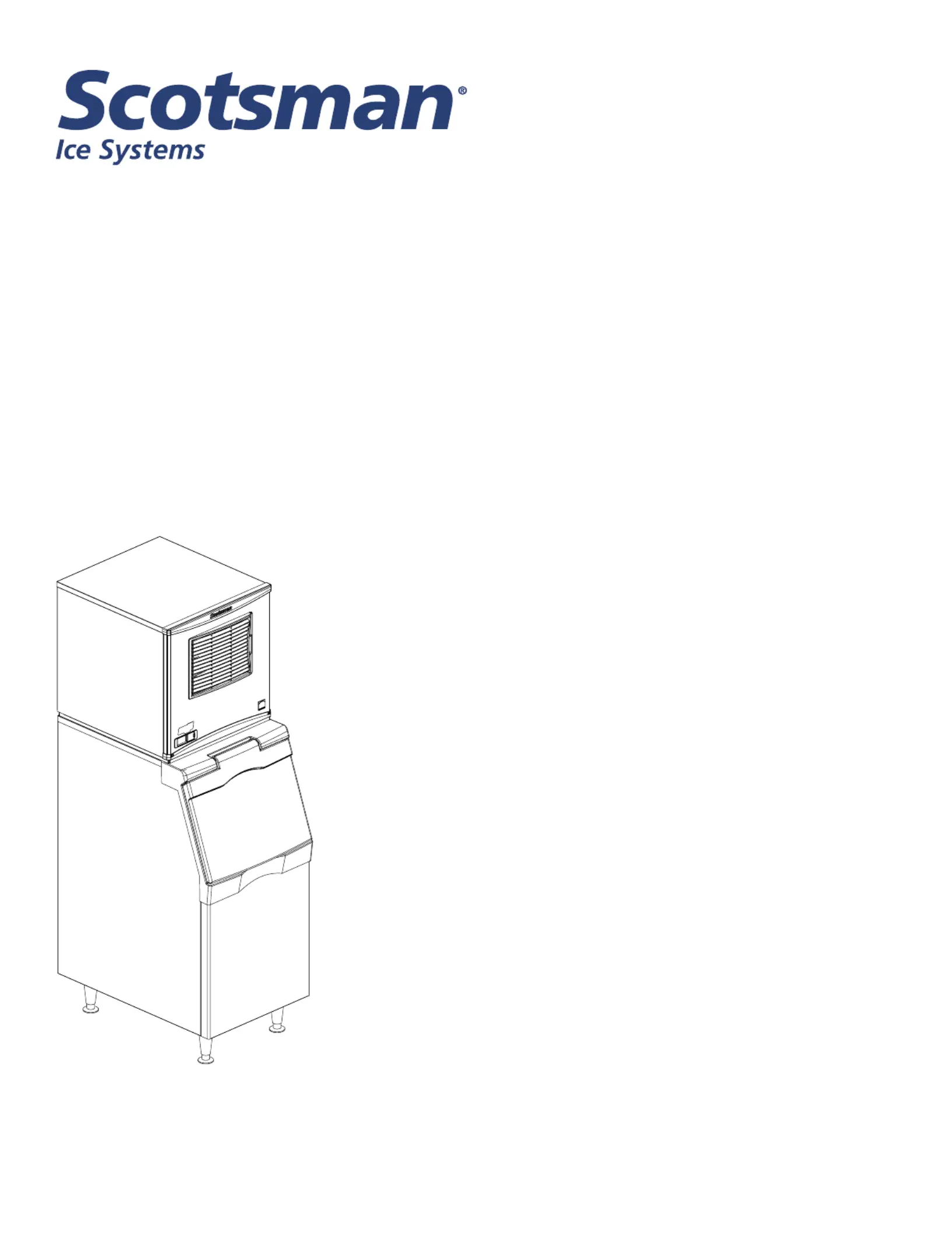
Installation and User’s Manual for
Modular Flaked and Nugget Ice Machines
Prodigy Plus D Series Models
F0522, F0822, F1222, F1522, N0422, N0622,
N0922 and N1322
Air Cooled, Water Cooled and Remote Air Cooled
Produkspesifikasjoner
| Merke: | Scotsman |
| Kategori: | Ikke kategorisert |
| Modell: | F1522-D |
Trenger du hjelp?
Hvis du trenger hjelp med Scotsman F1522-D still et spørsmål nedenfor, og andre brukere vil svare deg
Ikke kategorisert Scotsman Manualer

3 April 2025

3 April 2025

3 April 2025

3 April 2025

3 April 2025

3 April 2025

2 April 2025

2 April 2025

2 April 2025

2 April 2025
Ikke kategorisert Manualer
- Nabo
- Zummo
- Cleveland
- Michigan
- Gator Frameworks
- Mennekes
- Raya
- Enbrighten
- EXSYS
- Avantco
- OBH Nordica
- VAIS Technology
- Deaf Bonce
- Emga
- Eureka
Nyeste Ikke kategorisert Manualer

23 Oktober 2025

23 Oktober 2025

23 Oktober 2025

23 Oktober 2025

23 Oktober 2025

23 Oktober 2025

23 Oktober 2025

23 Oktober 2025

23 Oktober 2025

23 Oktober 2025