Westinghouse Oak Lane 6127500 Bruksanvisning
Westinghouse
Lettelse
Oak Lane 6127500
Les nedenfor 📖 manual på norsk for Westinghouse Oak Lane 6127500 (3 sider) i kategorien Lettelse. Denne guiden var nyttig for 21 personer og ble vurdert med 3.9 stjerner i gjennomsnitt av 11 brukere
Side 1/3
PENDANT MOUNTING AND WIRING INSTRUCTIONS
NOTE: Underwriters Laboratories (UL) does not require all fixtures to have ground wires. These fixtures
meet all UL specifications.
1. Turn off power at circuit box to avoid possible electric shock.
2. Thread mounting screws (A) into the cross bar (B).
3. Secure cross bar (B) to outlet box (C) with outlet box screws (D) (if applicable) (see fig. 1).
4. Attach the four support arms (E) to the fixture body (J) using the fixture screws 1 (K1). Then attach
decorative frame (S) to the bottom part of the support arms (E) with fixture screws 2 (K2). the
5. Remove and keep the decorative nut (R) from the cotter pin (L). Connect the bottom loop 3 (I3) from
the stem (V) to the fixture body (J) with cotter pin (L). Secure cotter pin (L) by decorative nut (R).
6. Open one link on bottom end of chain (H). Attach to the bottom end of chain (H) and fixture
loop 2 (I2).
Securely close link on chain (H).
7. Lace wires up through every other link on chain (H) then through canopy loop 1 (I1), canopy (F)
and nipple (G).
8. Open one link on top end of chain (H). Attach to canopy loop 1 (I1) and canopy (F). Securely close
link on chain (H).
9. Identify color coding of fixture wires (see fig. 3).
10. Connect the smooth wire with marking printed or molded from the fixture with the black wire
from outlet box (C) by wire connector (N), and wrap the wire connector (N) with electrical tape for
a more secure connection.
11. Connect the ribbed wire from the fixture with the white wire from the outlet box (C) by wire
connector (N), and wrap the wire connector (N) with electrical tape for a more secure connection.
12. Partially thread green grounding screw (O) into side hole (P) on cross bar (B).
13. Wrap grounding wire from fixture around green grounding screw (O) leaving enough excess
wire, then connect the excess grounding wire from the fixture with the grounding wire from outlet
box (C) by wire connector (N) (if applicable), then wrap the wire connector (N) with electrical tape
for a more secure connection.
14. Tighten green grounding screw (O). Do not over tighten.
15. Tuck wires inside outlet box (C).
16. Raise canopy (F) to ceiling over mounting screws (A).
17. Secure into place with cap nuts (Q).
SEMI-FLUSH MOUNTING AND WIRING INSTRUCTIONS
NOTE: Underwriters Laboratories (UL) does not require all fixtures to have ground wires. These fixtures
meet all UL specifications.
1. Turn off power at circuit box to avoid possible electric shock.
2. Thread mounting screws (A) into the cross bar (B).
3. Secure cross bar (B) to outlet box (C) with outlet box screws (D) (if applicable) (see fig. 2).
4. Attach the four support arms (E) to the fixture body (J) using the fixture screws 1 (K1). Then attach
decorative frame (S) to the bottom part of the support arms (E) with fixture screws 2 (K2). the
5. Remove and keep the decorative nut (R) from the cotter pin (L). Connect the loop 1 (I1) from
canopy (F) to the fixture body (J) by cotter pin (L). Secure cotter pin (L) by decorative nut (R).
6. Thread fixture wires through loop 1 (I1) and canopy (F).
7. Identify color coding of fixture wires (see fig. 3).
8. Connect the smooth wire with marking printed or molded from the fixture with the black wire
from outlet box (C) by wire connector (N), and wrap the wire connector (N) with electrical tape for
a more secure connection.
9. Connect the ribbed wire from the fixture with the white wire from the outlet box (C) by wire
connector (N), and wrap the wire connector (N) with electrical tape for a more secure connection.
10. Partially thread green grounding screw (O) into side hole (P) on cross bar (B).
11. Wrap grounding wire from fixture around green grounding screw (O) leaving enough excess wire,
then connect the excess grounding wire from the fixture with the grounding wire from outlet
box (C) by wire connector (N) (if applicable), then wrap the wire connector (N) with electrical tape
for a more secure connection.
12. Tighten green grounding screw (O). Do not over tighten.
13. Tuck wires inside outlet box (C).
14. Raise canopy (F) to ceiling over mounting screws (A).
15. Secure into place with cap nuts (Q).
FIXTURE ASSEMBLY INSTRUCTIONS
Warning: This fixture is for indoor use only.
1. Install lamp(s). Do not exceed recommended wattage.
2. Turn power back on at circuit box.
FIXTURE ASSEMBLY INSTRUCTIONS
Warning: This fixture is for indoor use only.
1. Install lamp(s). Do not exceed recommended wattage.
2. Turn power back on at circuit box.
WARNING
Turn off electricity to the mounting site before beginning installation.
Mounting instructions must be followed exactly as shown for the fixture to be safely supported.
CLEANING AND CARE
To clean, wipe fixture with soft cloth. Clean glass with mild soap. Spray from chemical cleaners can
discolor the finish of fixture. Do not use scouring pads, powders, steel wool or abrasive paper to
clean this fixture.
ORDERING PARTS
Keep this manual for future reference, and in case replacement parts are needed. Available parts can
be ordered from place of purchase. Use exact wording from diagrams when ordering parts.
FIGURE 2.
FIXTURE
WIRES:
Smooth
HOUSE
WIRES:
Black
(Hot)
HOUSE
WIRES:
White
(Neutral)
HOUSE
WIRES:
Bare
Copper
(Ground)
FIXTURE
WIRES:
Bare
Copper
(Ground)
FIXTURE
WIRES:
Ribbed
FIGURE 3.
W-765
042822
ASSEMBLY INSTRUCTIONS FOR INDOOR LIGHTING FIXTURE
Congratulations on your Westinghouse purchase. This fixture has been designed to give you many
years of beauty and service. For questions and comments, please visit www.westinghouselighting.
com/contact-us.
NOTE: Carefully unpack fixture and parts. Make sure all parts are included before discarding any pack-
ing materials (see figure 1).
Owner’s Manual
Indoor Lighting Fixture
Installation Instructions
FIXTURE WARRANTY
This Westinghouse lighting fixture is warranted against defects in material and workmanship for a period
of five years from purchase date. This warranty is in lieu of all other warranties expressed or implied.
This warranty does not cover acts of nature such as lightening damage, or corrosion and discoloration
of components, nor does it cover damages caused through abuse, improver installation, surges in
electric current, or acts of third parties.
This warranty does not cover the costs of removing and re-installing the lighting fixture.
If this product fails for any reason covered by this warranty, please contact us at www.westinghouse-
lighting.com/contact-us.
WARNING:
ELECTRICAL SHOCK CAN RESULT IN SERIOUS INJURY.
Read and follow instructions exactly as shown. If instructions are unclear, do not proceed.
Contact a qualified electrician. Read all instructions before beginning. Proper wiring is essen-
tial for safe operation of this fixture. When cutting or drilling into walls or ceilings, do not dam-
age electrical wiring, gas lines, or water lines. If any of the fixture or wiring components are
damaged, do not install fixture. Return to place of purchase.
For fixtures provided with 75° C or 90° C supply wire warning only. (These warnings are provid-
ed on the U.L. label and on the fixture carton.) Risk of fire. Most dwellings built before 1985
have supply wires rated 60° C. Consult a qualified electrician before installing.
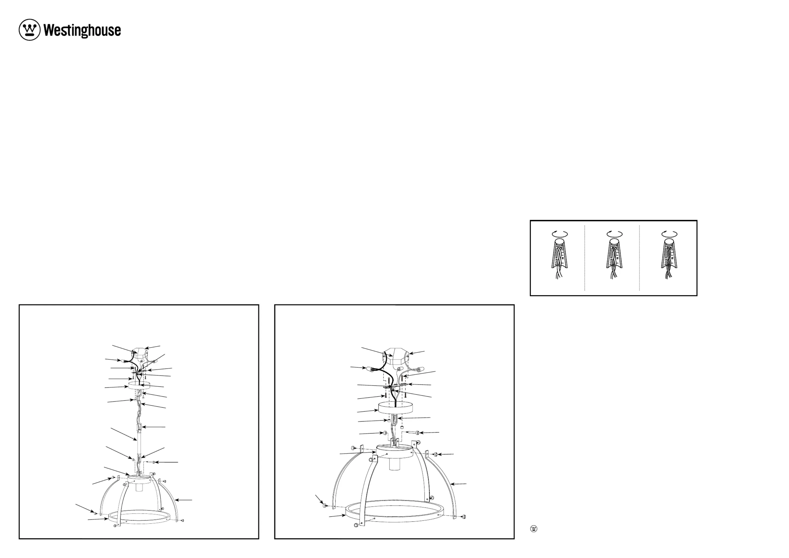
*NOT SUPPLIED
FIGURE 1.
For Pendant Mounting Option
*GROUND
WIRE
WIRE
CONNECTORS (N)
SIDE HOLE (P)
GREEN GROUNDING
SCREW (O)
LOOP 1 (I1)
NIPPLE (G)
LOOP 2 (I2)
LOOP 3 (I3)
COTTER PIN (L)
DECORATIVE
NUT (R)
STEM (V)
SUPPORT
ARMS (E)
CAP NUTS (Q)
FIXTURE
BODY (J)
FIXTURE
SCREW 1 (K1)
FIXTURE
SCREW 2 (K2)
DECORATIVE
FRAME (S)
CANOPY (F)
CHAIN (H)
CROSS BAR (B)MOUNTING SCREWS (A)
*OUTLET BOX SCREWS (D)
*OUTLET
BOX (C)
Line art shown may not exactly match the fixture enclosed.
However, the installation instructions do apply to this fixture.
*NOT SUPPLIED
FIGURE 2.
For Semi-flush Mounting Option
*GROUND
WIRE
WIRE
CONNECTORS (N)
SIDE HOLE (P)
GREEN GROUNDING
SCREW (O)
LOOP 1 (I1)
CAP NUTS (Q)
FIXTURE
BODY (J)
CANOPY (F)
CROSS BAR (B)
MOUNTING
SCREWS (A)
*OUTLET BOX
SCREWS (D)
*OUTLET
BOX (C)
FIXTURE
SCREW 1 (K1)
FIXTURE
SCREW 2 (K2)
SUPPORT
ARMS (E)
COTTER PIN (L)
DECORATIVE
NUT (R)
DECORATIVE
FRAME (S)
Line art shown may not exactly match the fixture enclosed.
However, the installation instructions do apply to this fixture.
Westinghouse Lighting, Philadelphia, PA 19154-1029, U.S.A. www.westinghouselighting.com
and Westinghouse are trademarks of Westinghouse Electric Corporation.
Used under license by Westinghouse Lighting. All Rights Reserved. Made in China
Produkspesifikasjoner
| Merke: | Westinghouse |
| Kategori: | Lettelse |
| Modell: | Oak Lane 6127500 |
Trenger du hjelp?
Hvis du trenger hjelp med Westinghouse Oak Lane 6127500 still et spørsmål nedenfor, og andre brukere vil svare deg
Lettelse Westinghouse Manualer

25 Februar 2025

25 Februar 2025

25 Februar 2025

25 Februar 2025

25 Februar 2025

25 Februar 2025

25 Februar 2025

25 Februar 2025

25 Februar 2025

25 Februar 2025
Lettelse Manualer
- Kern
- Rotolight
- BeamZ
- Milwaukee
- Kanlux
- Tesy
- Vimar
- Moen
- Lucide
- Nitecore
- WAC Lighting
- Luxli
- CSL
- DIO
- Integral LED
Nyeste Lettelse Manualer

9 April 2025

9 April 2025

8 April 2025

8 April 2025

8 April 2025

7 April 2025

6 April 2025

6 April 2025

6 April 2025

6 April 2025