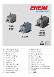
Zoeller M98 Bruksanvisning
Les nedenfor 📖 manual på norsk for Zoeller M98 (24 sider) i kategorien pumpe. Denne guiden var nyttig for 17 personer og ble vurdert med 3.6 stjerner i gjennomsnitt av 9 brukere
Side 1/24
1
© Copyright 2023 Zoeller
®
Co. All rights reserved.
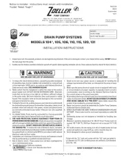
DRAIN PUMP SYSTEMS
MODELS 104*, 105, 106, 110, 115, 120, 131
INSTALLATION INSTRUCTIONS
P/N 017583
FM2336
0823
Supersedes
1221
Notice to Installer: Instructions must remain with installation.
MODEL: ______________________
DATE CODE: __________________
DATE INSTALLED: _____________
When making changes to this FM, be sure to also make changes to the Spanish and French version and also the FW0107
if the 104 pump is changed. Also, if the changes will aect the model 1104, FM2366 for Dayton will also be aected.
1. Inspect your unit. Occasionally, products are damaged during shipment. If the unit is damaged, contact your dealer before using. DO NOT remove
the test plugs from the pump.
2. Carefully read the literature provided to familiarize yourself with specic details regarding installation and use. These materials should be retained for future reference.
1. To reduce the risk of electrical shock, a properly grounded receptacle
of grounding type must be installed and protected by a ground fault
circuit interrupter (GFCI) and in accordance with National Electrical
Code and local codes. (SEE WARNING BELOW)
2. Make certain that the receptacle is within the reach of the pump’s
power supply cord. DO NOT USE AN EXTENSION CORD. Extension
cords that are too long or too light do not deliver sufcient voltage
to the pump motor. But more important, they could present a safety
hazard if the insulation were to become damaged or the connection
end were to fall into the sump.
3. Testing for Ground. As a safety measure, each electrical outlet should
be checked for ground using an Underwriters Laboratory Listed circuit
analyzer which will indicate if the power, neutral and ground wires
are correctly connected to your outlet. If they are not, call a qualied
electrician.
4. For Added Safety. Pump must be connected to a 3-prong grounded
outlet interrupter device (ground fault circuit interrupter).
5. FOR YOUR PROTECTION, ALWAYS DISCONNECT PUMP FROM ITS
POWER SOURCE BEFORE HANDLING. Single phase pumps are supplied
with a 3-prong grounded plug to help protect you against the possibility
of electrical shock. DO NOT, UNDER ANY CIRCUMSTANCES, REMOVE
THE GROUND PIN. To reduce the risk of electrical shock, a properly
grounded receptacle of grounding type must be installed and protected
by a ground fault circuit interrupter (GFCI) in accordance with national
electrical code and local codes.
6. Installation and checking of electrical circuits and hardware should
only be performed by a qualied licensed electrician.
7. Risk of electric shock - These pumps have not been investigated for
use in swimming pool areas.
8. Prop65 Warning for California residents:
: Cancer and Reproductive Harm-
www.P65Warning.ca.gov.
1. Check to be sure your power source is adequate for handling the
voltage requirements of the motor, as indicated on the pump or basin
plate.
2. Make sure the pump electrical supply circuit is equipped with fuses
or circuit breakers of proper capacity. A separate branch circuit is
recommended, sized according to the National Electrical Code for
the current shown on the pump name plate.
3. All plumbing (discharge and vent lines) must be installed to meet local
codes. Unit must be vented. DO NOT USE AN AUTOMATIC PLUMBING
VENT DEVICE SIMILAR TO A "PRO-VENT". Some states require this
product to be installed by a licensed plumber.
4. Repair and service should be performed by Zoeller Pump Company
Authorized Service Station only.
5. CHECK VALVE MUST BE USED TO REDUCE UNNECESSARY CYCLING
OF PUMP. Check valve must be purchased separately on model 104
only.
6. Dewatering pumps are not designed or intended for handling raw
sewage.
7. Maximum operating temperature for 105-131 Drain Pumps must not
exceed 130 °F (54 °C). 104 Drain Pumps are not to exceed 110 °F (43
°C).
8. For health reasons, do not unplug, turn off, or disable pump and use
pump tank system as a way to ll up a sink or laundry tray, etc.
9. Unit is designed for above ground installation only.
SEE BELOW FOR LIST OF WARNINGS
CAUTION
SEE BELOW FOR LIST OF CAUTIONS
REFER TO WARRANTY ON PAGE 2.
Pumps with the “UL” mark and pumps with the “US” mark are tested to
UL Standard UL778. CSA Certified pumps are certified to CSA Standard
C22.2 No. 108.
Product information presented here reflects conditions at time of publication. Consult factory regarding discrepancies or inconsistencies.
MAIL TO: P.O. BOX 16347 • Louisville, KY 40256-0347
SHIP TO: 3649 Cane Run Road • Louisville, KY 40211-1961
Tel: (502) 778-2731 • 1 (800) 928-PUMP
Visit our website:
zoellerpumps.com
Trusted. Tested. Tough.
®
MEETS UPC
COMPLIES WITH ASME A112.3.4
AND CSA B45.9.
P/N 018535-E
* MODEL 104 IS NOT
UPC APPROVED.
Produkspesifikasjoner
| Merke: | Zoeller |
| Kategori: | pumpe |
| Modell: | M98 |
Trenger du hjelp?
Hvis du trenger hjelp med Zoeller M98 still et spørsmål nedenfor, og andre brukere vil svare deg
pumpe Zoeller Manualer
26 August 2025

26 August 2025
pumpe Manualer
- Sauermann
- Einhell
- Hayward
- SKS
- Grundfos
- Laguna
- Draper
- SereneLife
- Biltema
- Toolcraft
- Karcher
- Ryobi
- POLARIS
- Eurom
- Fluke
Nyeste pumpe Manualer
6 Oktober 2025
6 Oktober 2025
6 Oktober 2025
6 Oktober 2025
6 Oktober 2025
5 Oktober 2025

5 Oktober 2025
5 Oktober 2025
5 Oktober 2025

5 Oktober 2025