Advantech ICR-2631 Bruksanvisning

Advantech Ruter ICR-2631

Les nedenfor 📖 manual på norsk for Advantech ICR-2631 (44 sider) i kategorien Ruter. Denne guiden var nyttig for 19 personer og ble vurdert med 4.5 stjerner i gjennomsnitt av 2 brukere

Side 1/44
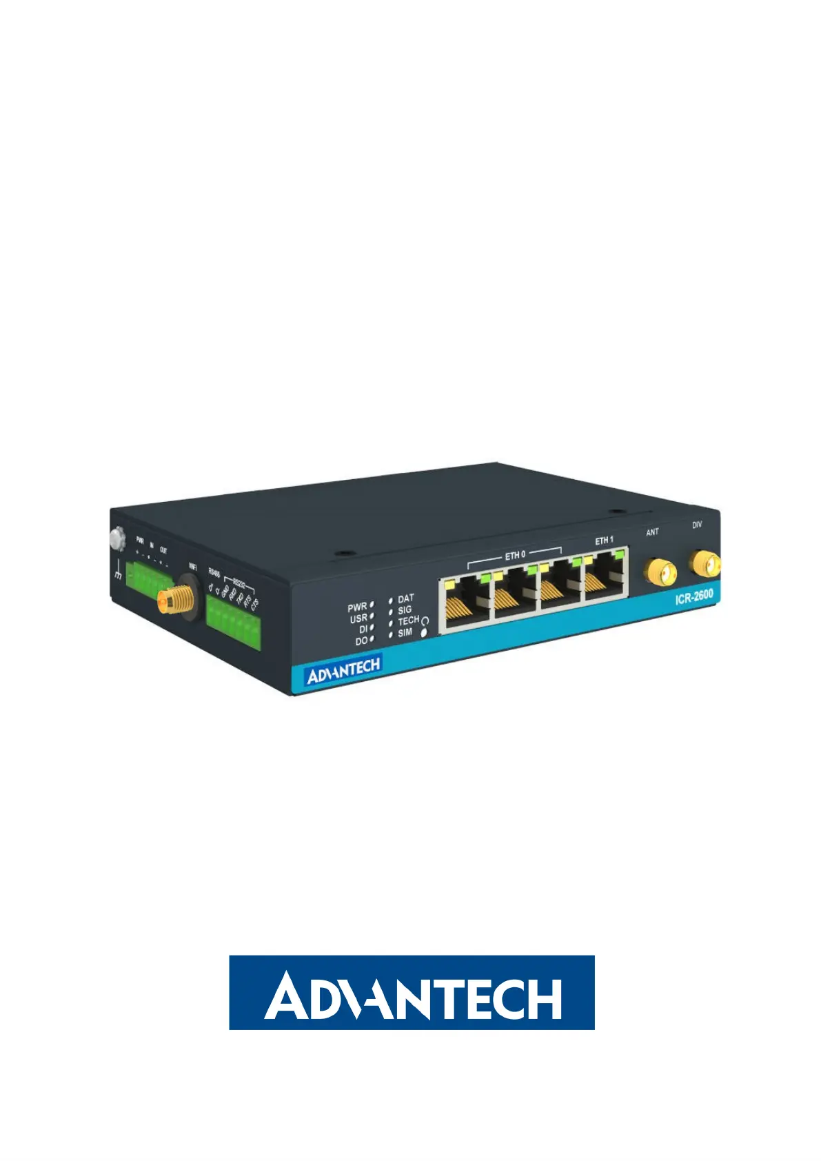
LTE Industrial Router
ICR-2631
USER MANUAL
ICR-2631
© 2023 Advantech Czech s.r.o. No part of this publication may be reproduced or transmitted in any form or by
any means, electronic or mechanical, including photography, recording, or any information storage and retrieval
system without written consent. Information in this manual is subject to change without notice, and does not
represent a commitment on the part of Advantech.
Advantech Czech s.r.o. shall not be liable for incidental or consequential damages resulting from the furnish-
ing, performance, or use of this manual.
All brand names used in this manual are the registered trademarks of their respective owners. The use of
trademarks or other designations in this publication is for reference purposes only and does not constitute an
endorsement by the trademark holder.
i
ICR-2631
Used symbols
Danger – Information regarding user safety or potential damage to the router.
Attention – Problems that can arise in specific situations.
Information, notice – Useful tips or information of special interest.
Advantech Czech s.r.o., Sokolska 71, 562 04 Usti nad Orlici, Czech Republic
Document No. MAN-0063-EN, revision from June 20, 2023. Released in the Czech Republic.
ii
ICR-2631
Contents
1 Product Overview 2
1.1 Product Introduction ................................. 2
1.2 Product Usage Examples .............................. 3
1.3 Hardware Overview ................................. 5
1.4 Order Codes ..................................... 7
1.5 Product Revisions .................................. 7
1.6 Package Contents .................................. 8
1.7 Product Dimensions ................................. 9
1.8 Mounting Recommendations . . . . . . . . . . . . . . . . . . . . . . . . . . . . 11
1.9 Wall Mounting ..................................... 12
1.10 DIN Rail Mounting .................................. 13
1.11 Product Label ..................................... 14
2 Hardware Functionality 15
2.1 SIM Card Slots .................................... 15
2.2 Antennas ....................................... 16
2.3 Ethernet Interfaces .................................. 16
2.4 Power Supply ..................................... 17
2.5 I/O Port Interfaces .................................. 18
2.6 Serial Interfaces ................................... 19
2.7 LED Status Indication ................................ 20
2.8 Reset Functions ................................... 21
3 First Use 22
3.1 Accessories Connection ............................... 22
3.2 Router Configuration ................................. 22
4 Technical Specifications 24
4.1 Basic Parameters ................................... 24
4.2 Standards and Regulations ............................. 25
4.3 Type Tests and Environmental Conditions . . . . . . . . . . . . . . . . . . . . . 26
4.4 Parameters of Cellular Module ........................... 27
4.5 Parameters of WiFi .................................. 28
4.6 Parameters of I/O Ports ............................... 29
4.7 Parameters of Serial Interfaces ........................... 29
4.8 System Configuration ................................ 30
Appendix A: Troubleshooting 31
iii
ICR-2631
Appendix B: Customer Support 34
Appendix C: Regulatory & Safety Information 35
Appendix D: Related Documents 37
iv
ICR-2631
List of Figures
1 Access to the Internet from LAN .......................... 3
2 Backed up Access to the Internet .......................... 3
3 Using VPN Tunnel .................................. 4
4 Serial Gateway .................................... 4
5 Hardware Overview of the Router .......................... 5
6 Router Dimensions – Top, Side and Front View with Wall Mount Clip . . . . . . 9
7 Router Dimensions – Top, Side and Front View with DIN Rail Clip . . . . . . . . 10
8 Screwed Wall Mounting Clip ............................. 12
9 Position of the DIN Rail Clip ............................. 13
10 Removing Router from the DIN Rail ......................... 13
11 Product Label ..................................... 14
12 SIM Cards Insertion ................................. 15
13 Ethernet Connector Pinout .............................. 16
14 Connection of Power Supply ............................ 17
15 Position of the Grounding Screw .......................... 17
16 I/O Connector Pinout ................................. 18
17 Functional Scheme of the Binary Interface . . . . . . . . . . . . . . . . . . . . . 18
18 RS485 and RS232 Pinout .............................. 19
19 Resetting the Router ................................. 21
20 Router’s Web Interface ................................ 23
v
ICR-2631
List of Tables
1 Hardware Overview of the Router .......................... 6
2 Order Codes Overview ................................ 7
3 HW Revisions History ................................ 7
4 Contents of Package ................................. 8
5 Ethernet Connector Pinout Description ....................... 16
6 Power Supply Pinout ................................. 17
7 I/O Ports Pinout .................................... 18
8 Connection of RS485 ................................ 19
9 Connection of RS232 ................................ 19
10 LED Status Indication ................................ 20
11 Basic Parameters ................................... 24
12 Standards and Regulations ............................. 25
13 Type Tests and Environmental Conditions . . . . . . . . . . . . . . . . . . . . . 26
14 Technical Parameters of Cellular Module . . . . . . . . . . . . . . . . . . . . . . 27
15 Technical Parameters of WiFi . . . . . . . . . . . . . . . . . . . . . . . . . . . . 28
16 Electrical Characteristics of Binary Input ...................... 29
17 Parameters of Serial Interfaces ........................... 29
18 System Configuration ................................ 30
1
ICR-2631
1.2 Product Usage Examples
The router is primarily intended for these basic situations:
I. Access to the Internet from LAN
Figure 1: Access to the Internet from LAN
II. Backed up access to the Internet (from LAN)
Figure 2: Backed up Access to the Internet
3
ICR-2631
III. Secure networks interconnection or using VPN
Figure 3: Using VPN Tunnel
IV. Serial Gateway
Figure 4: Serial Gateway
4
ICR-2631
1.3 Hardware Overview
The router case preview is shown in Figure . A short description of hardware parts of the
5
router is listed in Table , including the links to the chapters with a detailed description.1
Figure 5: Hardware Overview of the Router
# Item/Caption Type Description
1 Grounding
screw
M3 Pay attention to proper grounding; see Chapter .2.4
2 PWR
IN/OUT
6-pin
terminal
Power supply, binary input, and binary output interfaces.
See Chapter , Chapter , Chapter for more infor-
2.4 2.5 2.6
mation, Chapter for I/O parameters, and Chapter4.6 4.7
for serial interface parameters.
3 WiFi RP-SMA
female
Connector for the WiFi antenna; see Chapter and
2.2
Chapter for WiFi parameters.4.5
4 RS485/RS232 7-pin
terminal
RS232 & RS485 serial interfaces; see Chapter .2.6
Continued on the next page
5
ICR-2631
Continued from previous page
# Item/Caption Type Description
5 LEDs - Status LED indication; see Chapter .2.7
6 RST - Button to reboot the router or to restore the default
configuration; see Chapter .
2.8
7 ETH0
ETH1
3 RJ45×
1 RJ45×
100 MB Ethernet switch connections for the first LAN and
Ethernet connection for the second LAN; see Chapter .
2.3
8 ANT SMA
female
Connector for the main antenna of the cellular module; see
Chapter .
2.2
9 DIV SMA
female
Connector for the second antenna of the cellular module
(required for the MIMO DL); see Chapter .
2.2
10 SIM slots Micro SIM Two SIM card slots; see Chapter .2.1
11 DIN clip - DIN rail clip, as standard accessories; seenot included
Chapter .
1.10
12 Wall clip - Wall mounting clip, included as standard accessories; see
Chapter .
1.9
Table 1: Hardware Overview of the Router
6
ICR-2631
1.4 Order Codes
Order codes overview is shown in the table below.
Order code Features – interfaces
ICR-2631 LTE Cat.4 with 3G/2G fallback cellular module, 64 MB NOR Flash, 3x ETH0
switch, 1x ETH1, 1x RS232, 1x RS485, 1x Binary Input, 1x Binary Output,
2x SIM reader
ICR-2631 LTE Cat.4 with 3G/2G fallback cellular module, 64 MB NOR Flash, 3x ETH0W
switch, 1x ETH1, 1x RS232, 1x RS485, 1x Binary Input, 1x Binary Output,
2x SIM reader
Table 2: Order Codes Overview
1.5 Product Revisions
For the product revision history, see the table below. The revision number is printed on the
packaging and product labels.
The router GUI can also display the product revision under Status -> General -> System
Information -> Product Revision. Please note that the default revision (Rev.1.0) is unavailable
here.
Rev.# Description
1.0 Initial version (revision not printed on the labels).
2.0 New design of the mainboard; see for details.
PCN-2023-05
Table 3: HW Revisions History
7
ICR-2631
1.6 Package Contents
The standard set of router includes items listed in the following table:
Item# Description Figure Q’ty
1 Router 1 pcs
2 Wall mounting clip with screws 1 set
3
6-pin terminal block for power sup-
ply, digital input and digital output (de-
ployed on the router)
1 pcs
47-pin terminal block for RS485 and
RS232 (deployed on the router) 1 pcs
5 Printed 1 pcsQuick Start Guide Leaflet
Table 4: Contents of Package
8
ICR-2631
Variant with DIN Rail Clip
Figure 7: Router Dimensions – Top, Side and Front View with DIN Rail Clip
10
ICR-2631
1.8 Mounting Recommendations
The router can be placed:
on a at surface,
on a wall using the wall mounting clip (see Chapter ),
1.9
on a DIN rail EN 60715 with the metal DIN rail clip (see Chapter )1.10
For most applications with a built-in router within a switchboard, it is possible to recognize
two kinds of environments:
A non-public, industry environment of low voltage with high interference,
a public environment of low voltage and without high interference.
For both of these environments, it is possible to mount the router to a switchboard, af-
ter which there is no need to have examination immunity or issues in connection with EMC
according to EN 61439-1:2011.
In compliance with the EN 61439-1:2011 specification, it is necessary to observe the
following assembly instructions for a router attached to a switchboard:
For whip antennas it is recommended to observe a minimum distance of 6 cm from ca-
bles and metal surfaces on every side in order to avoid interference. When using an
external antenna separate from the switchboard it is necessary to fit a lightning conduc-
tor.
When mounting a router on sheet-steel we recommend using a cable antenna.
For all cables, we recommend to bind the bunch, and for this we recommend:
The length of the bunch (the combination of power supply and data cables) should
be a maximum 1.5 m. If the length of data cables exceeds 1.5 m or if the cable is
leading towards the switchboard, we recommend installing surge protectors.
Data cables must not have a reticular tension of 230 V/50 Hz or 120 V/60 Hz.∼ ∼
Sufficient space must be left between each connector for the handling of cables,
To ensure the correct functioning of the router we recommend the use of an earth-
bonding distribution frame for the grounding of the grounding screew, see Chapter .
2.4
11
ICR-2631
1.9 Wall Mounting
The wall mounting clip is supplied with the router as standard accessories.
The router can be screwed to a wall (or another surface) using the wall mounting clip.
There are two wholes on the clip with a diameter of 4 millimeters. For detailed information
about the mounting dimensions see Figure in Chapter .
6 1.7
When mounting the wall mounting clip, tighten the screws with max. torque of 0.4 Nm.
Figure 8: Screwed Wall Mounting Clip
12
ICR-2631
1.10 DIN Rail Mounting
The DIN rail clip is not supplied with the router as standard accessories, but it can be ordered
by the order code .BB-DIN-ICR32
The DIN rail clip is suitable for a DIN rail according to EN 60715 standard only. The default
position of the clip is shown in Figure .
9
When mounting the DIN rail clip, tighten the screws with max. torque of 0.4 Nm.
Figure 9: Position of the DIN Rail Clip
To remove the router from the DIN rail it is necessary to lightly push down the router so
that the bottom part of the DIN rail clip hitched to the DIN rail get out of this rail and then fold
out the bottom part of the router away from the DIN rail, see Figure .
10
Figure 10: Removing Router from the DIN Rail
13
ICR-2631
1.11 Product Label
The figure below shows an example of the product labels with all the information printed
on them.
Figure 11: Product Label
14
ICR-2631
2. Hardware Functionality
See Chapter for the product hardware overwiew. Table lists a short description of the
1.3 1
hardware, including the links to the chapters with a detailed description.
2.1 SIM Card Slots
Slots for two SIM cards are located on the router under a metal cover. If you intend to use
this device to communicate over a cellular network, please place an activated data-provisioned
SIM card into the SIM card reader.
You can install two SIM cards simultaneously to utilize the switching feature. The SIM cards
may have different APNs (Access Point Names) adjusted. The SIM card changing procedure
is described below. Enter the PIN in the router’s web interface if the PIN is required for the
SIM (Administration Unlock SIM Card-> ).
Type of SIM card: Micro SIM (3FF) 15.0 x 12.0 x 0.76 mm.
Inserting the SIM card:
Always disconnect the router from the power supply before handling the SIM card.
Unscrew two screws on the SIM card cover and remove the cover.
To remove an inserted SIM card, use the flat end of a spudger, or your fingernail,
press the SIM card slightly into its slot until you hear a click. After hearing this click,
release the card, and it will pop out of its slot.
To insert a SIM card push card into the slot until it clicks into place.
Place back the cover and fix it by two screws.
Figure 12: SIM Cards Insertion
15
ICR-2631
2.2 Antennas
Connect cellular antennas to the router to main (ANT) and secondary (DIV) SMA female
connectors on the front panel. Connect WiFi antenna to the WiFi RP-SMA female connector
on the side of the router.
Only run the router with a cellular antenna connected to the main antenna connector, as
the energy from the transmission is effectively reflected by the open end and can damage
the equipment.
The DIV cellular antenna is required for the MIMO DL functionality.
Recommended tightening moment for screwing the antenna to the SMA female connectors is
0.9 Nm.
2.3 Ethernet Interfaces
The panel socket of RJ45 is used for Ethernet interface. The pinout of the socket is shown
in Figure and described in Table .
13 5
Figure 13: Ethernet Connector Pinout
Pin Signal mark Description
1 Tx+ Transmit Data+ (positive pole)
2 Tx- Transmit Data- (negative pole)
3 Rx+ Receive Data+ (positive pole)
4 —
5 —
6 Rx- Receive Data- (negative pole)
7 —
8 —
Table 5: Ethernet Connector Pinout Description
The isolation barrier of the Ethernet ports against the ground is 1500 V.
16
ICR-2631
2.4 Power Supply
The pins of power supply are physically connected to the 6-pin terminal block panel socket
located on the left panel. The connection of power supply is shown in Figure and described
14
in Table .6
Figure 14: Connection of Power Supply
Pin Signal mark Description
1 PWR(+) Positive pole of DC supply voltage (+9 to +48 V DC)
2 PWR(-) Negative pole of DC supply voltage
Table 6: Power Supply Pinout
Required power supply voltage for the router is between +9 V and +48 V DC, see the
connection scheme on Figure . Protection against reversed polarity without signaling is
14
built into the router. For correct operation it is necessary that the power source is able to
supply a peak current of 1 A.
Unit has to be supplied by a power supply specified as a Limited Power Source (LPS) or
CEC/NEC Class 2 source of supply.
The metal case of the router is not connected to the negative pole of the power sup-
ply (common pole). If recommended for the installation environment, protect the router by
grounding it properly by the grounding screw, see Figure .
15
Figure 15: Position of the Grounding Screw
17
ICR-2631
2.6 Serial Interfaces
The pins of RS232 and RS485 serial interfaces are physically connected to the 7-pin ter-
minal block panel socket located on the left panel. The pinout of this connector is described in
Figure and in Table , resp. Table .
18 8 9
Figure 18: RS485 and RS232 Pinout
Pin Signal mark Description
1 D (+) In/Out
2 D (-) In/Out
3 GND Ground (common with RS232)
Table 8: Connection of RS485
Pin Signal mark Description
3 GND Ground (common with RS485)
4 RXD Received Data
5 TXD Transmit Data
6 RTS Request to Send
7 CTS Clear to Send
Table 9: Connection of RS232
The serial interfaces are not eletrically isolated from the router.
19
ICR-2631
2.7 LED Status Indication
There are LED indicators on the front panel of the router to provide router status informa-
tion. Moreover, ETH connector, has two additional LEDs providing information about the port
status.
Caption Color State Description
PWR Green
Green
Green
On
Blinking
Fast blinking
The router is booting up.
The router booted up and is ready.
The router firmware is being updated.
USR Green The function of this LED is user-defined.
DI Green On The binary input is active.
DO Green On The binary output is active.
DAT Green Blinking Cellular communication is in progress.
SIG Green On
Blinking
Fast blinking
Good cellular signal.
Fair cellular signal.
Poor cellular signal.
TECH Green On
Blinking
Fast blinking
The active SIM uses 4G technology.
The active SIM uses 3G technology.
The active SIM uses 2G technology.
SIM Green On
Blinking
Fast blinking
SIM1 is active for the cellular connection.
SIM2 is active for the cellular connection.
A SIM issue (missing card or PIN not entered).
ETH0
ETH1
Green
Green
On
Off
Selected 100 Mbps bit rate.
Selected 10 Mbps bit rate.
ETH0
ETH1
Orange
Orange
Orange
On
Blinking
Off
The network cable is connected.
Data transmission.
The network cable is not connected.
Table 10: LED Status Indication
20
ICR-2631
2.8 Reset Functions
Consider creating a router configuration backup before performing the routers factory
reset.
The RST button can be used in three different scenarios:
: Hold theReset RST button for ; the router will reboot, applying itsless than 4 seconds
customized configuration. The router reset can be initiated by clicking the Reboot menu
item in the router web GUI.
Factory Reset: To restore the default factory configuration of the router, press and hold
the button for . After that, the LED turns off and onRST more than 4 seconds PWR
again. We recommend holding the button for 1 second after turning on the PWRRST
LED.
: If the router cannot boot up due to the incorrect configu-Emergency Factory Reset
ration, turn off the router (disconnect the power supply). Then, push and hold the RST
button, turn on the router and hold the RST button for . The routerat least 10 seconds
configuration will be set to the default one.
It is necessary to use a narrow screwdriver or any other small tool to press the RST button.
Figure 19: Resetting the Router
21
ICR-2631
3. First Use
3.1 Accessories Connection
Before putting the router into operation, it is necessary to connect all the components
required to run your applications; see Chapter for the hardware overview. Remember to
1.3
insert a SIM card for the cellular connection; see Chapter .2.1
Do not run the router without antenna connected to the main antenna connector as the
energy from the transmission is effectively reflected by the open end and can damage
the equipment.
3.2 Router Configuration
Initial router configuration can be made via a web browser on your PC. Here you can
perform router monitoring, configuration, and administration.
Connect the power supply to the router, see Chapter , and the router will boot up.
2.4
By default, the router will automatically log on to the default APN of the inserted SIM card.
Configure your PC to get the IP settings automatically from the network. Connect the network
card of your PC to the default router LAN interface, Ethernet port ETH0, and the DHCP server
will assign an IP address to your PC.
To get the router web interface, enter the address in a web browser.
Please note that usage of the HTTPS protocol for secure communication over the network is
required.
There is just the user account created on the router by default. See the product
label default passwordon the router for its 1. Log in to the web interface with the
user and his password. If logged in successfully, the user will have access to the router web
interface, see Figure . See the router configuration manual for a detailed description and
20 [1]
examples of the router configuration.
After logging on to the device for the first time, we strongly recommend changing the
default password due to security reasons.
For security reasons, we recommend regularly updating the router’s firmware to the latest
version. Downgrading the firmware to an older version than the production version or
uploading firmware intended for a different device may cause the device’s malfunction.
All routers have the client pre-installed by default. The activated clientWebAccess/DMP
periodically uploads router identifiers and configuration to the WebAccess/DMP server.
See the configuration manual , chapter
[1] Basic Information -> WebAccess/DMP Config-
uration, for more information.
1Use the password if the router’s label does not contain a unique password.
22
ICR-2631
Figure 20: Router’s Web Interface
A detailed description of the router settings in the web interface can be found in the configura-
tion manual of the router.[1]
23
ICR-2631
4.2 Standards and Regulations
The router complies with the following standards and regulations:
Parameter Description
Radio EN 301 893, EN 300 328, EN 301 511, EN 301 908-1, EN 301
908-2, EN 301 908-13
EMC EN 301 489-1, EN 301 489-17, EN 301 489-52, EN 61000-4-2,
EN 61000-4-3, EN 61000-4-4, EN 61000-4-5, EN 61000-4-6,
IEC 61000-6-2, IEC 61000-6-3, EN 55032
Safety EN IEC 62368-1, IEEE 802.3
Transportation E-Mark (E8), homologation number: 10R - 06 140281
National CE, UKCA compliant
Environmental REACH, RoHS3 and WEEE compliant
Table 12: Standards and Regulations
1For product revision 2.0 and higher.
25
ICR-2631
4.3 Type Tests and Environmental Conditions
Phenomena Test Description Test levels
ESD EN 61000-4-2 Enclosure CD 6 kV, L3±
RF field AM
modulated
EN 61000-4-3 Enclosure 20 V/m, 80 MHz-1 GHz, LX
10 V/m, 1 GHz-6 GHz, L3
Fast transient EN 61000-4-4 DC port
ETH - FTP
Binary input
Binary output
RS232
RS485
±1 kV, 5/50 Tr/Th ns, 100 kHz, L2
±1 kV, 5/50 Tr/Th ns, 100 kHz, L3
Surge EN 61000-4-5 ETH
RS485
±1 kV, 1.2/50(8/20) Tr/Th us, L2
RF conducted EN 61000-4-6 DC port
ETH
I/O ports
RS232
RS485
10 V, 0.15-80 MHz, 80%AM(1kHz), L3
Radiated emission EN 55032 Enclosure Class B, 30 MHz-1 GHz, 1 GHz-6 GHz
Conducted
emission
EN 55032 DC power port
Ethernet ports
Serial ports
RS232
RS485
Class B, 150 kHz-30 MHz
Dry heat EN 60068-2-2 Operating
Storage
Test Bb, storage +75 C
Test Bd, operation +85 C
Cold EN 60068-2-1 Operating
Storage
Test Ab, storage -40 C
Test Ad, operation -40 C
Variation of
temperature
EN 60068-2-14 Test Nb, -40 C / +75 C, 3h/3h, 2 cycles, 3 K/min
Dry heat, cyclic EN 60068-2-30 +55 C / +25 C, rel. humidity 95 %, 6 h-6 h
Table 13: Type Tests and Environmental Conditions
26
ICR-2631
4.4 Parameters of Cellular Module
Parameter Description
Antenna Connector type: SMA
Impedance: 50
LTE parameters LTE: LTE Cat.4, 3GPP Rel. 11
FDD frequencies: B28A (700 MHz), B20 (800 MHz),
B8 (900 MHz), B7 (2600 MHz), B3 (1800 MHz), B1 (2100 MHz)
TDD frequencies: B41 (2500 MHz), B40 (2300 MHz),
B38 (2600 MHz)
Bit rates: up to 150 Mbps (DL), 50 Mbps (UL)
HSPA+/UMTS
parameters
Supported frequencies: B8 (900 MHz), B1 (2100 MHz)
Bit rates: up to 42 Mbps (DL) / 5.76 Mbps (UL)
EDGE/GPRS
parameters
Supported frequencies: B8 (900 MHz), B3 (1800 MHz)
Bit rates: up to 296 kbps (DL) / 236.8 kbps (UL)
Table 14: Technical Parameters of Cellular Module
27
ICR-2631
4.5 Parameters of WiFi
Parameter Description
Supported Standards IEEE802.11 a/b/g/n/ac
Antenna connector 1x RP-SMA
Input impedance: 50
Data Rate 802.11b: 1, 2, 5.5, 11Mbps
802.11a/g: 6, 9, 12, 18, 24, 36, 48, 54 Mbps
802.11n: Max. 72 Mbps @ 20 MHz channel
802.11n: Max. 150 Mbps @ 40 MHz channel
Frequency Ranges 2.4 GHz ISM Bands 2.412-2.472 GHz
5.15-5.25 GHz (FCC UNII-low band) for US/Canada and EU
5.25-5.35 GHz (FCC UNII-middle band) for US/Canada and EU
5.47-5.725 GHz for EU
5.725-5.825 GHz (FCC UNII-high band) for US/Canada
Modulation DSSS, OFDM, DBPSK, DQPSK, CCK, 16-QAM, 64-QAM
2.4 GHz Channels 1, 2, 3, 4, 5, 6, 7, 8, 9, 10, 11, 12, 13
5 GHz Channels 36, 38, 40, 42, 44, 46, 48, 52, 56, 60, 64, 100, 104, 108, 112,
116, 120, 124, 128, 132, 136, 140, 149, 153, 157, 161, 165
Type of Device Access point (AP)
Station (STA)
Multirole (STA&AP)
Security – Standards WPA, WPA2, WPA3, 802.1X
Security – Encryption WEP, TKIP, AES
TX Power Max. 18 dBm @ 2.4 GHz
Max. 15 dBm @ 5 GHz
Table 15: Technical Parameters of WiFi
28
ICR-2631
4.6 Parameters of I/O Ports
Electrical characteristics of the binary input are in Table . Status of the binary input is
16
reported in the GUI on page or can be retrieved in the Shell viaGeneral Status
command.
command output Voltage Web interface status
0 0.8 V (0.5 mA)) On
1 2 V Off
Table 16: Electrical Characteristics of Binary Input
The maximum binary output load is at .100 mA 9 – 48 V
4.7 Parameters of Serial Interfaces
Supported parameters of the RS232 and RS485 interfaces, which can be configured in
Expansion Port 1 Expansion Port 2resp. menu items, are in Table .
17
Parameter Description
Baudrate 300, 600, 1200, 2400, 4800,
9600, 19200, 38400, 57600,
115200, 230400.
Data Bits 5, 6, 7, 8.
Parity none, even, odd.
Stop Bits 1, 2.
Flow Control none, hardware.
Table 17: Parameters of Serial Interfaces
29

Produkspesifikasjoner

Merke: Advantech
Kategori: Ruter
Modell: ICR-2631

Trenger du hjelp?

Hvis du trenger hjelp med Advantech ICR-2631 still et spørsmål nedenfor, og andre brukere vil svare deg


Ruter Advantech Manualer

Ruter Manualer

Nyeste Ruter Manualer