Berker 20291909 Bruksanvisning
Les nedenfor 📖 manual på norsk for Berker 20291909 (2 sider) i kategorien vegguttak. Denne guiden var nyttig for 12 personer og ble vurdert med 4.6 stjerner i gjennomsnitt av 6.5 brukere
Side 1/2

6LE007114A
Operating and
assembly instructions
Bedienings- en
montagehandleiding
z
i
Berker GmbH & Co. KG - Klagebach 38 - 58579 Schalksmühle/Germany - Tel. + 49 (0) 23 55/90 5-0 - Fax + 49 (0) 23 55/905-3111 - www.berker.com - 6LE007114A - 01/2019
2029 ..
Room thermostat with swich
heating/cooling
Kamerthermostaat med schakelaar
verwarmen / koelen
Safety instructions
Electrical equipment may only be installed and
assembled by a qualifi ed electrician in accord-
ance with the relevant installation standards,
guidelines, regulations, directives, safety and
accident prevention regulations of the country.
Failure to comply with these instructions may
result in damage to the device, fi re or other
hazards.
These instructions are an integral component
of the product and must be retained by the end
user.
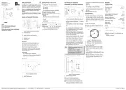
Design and layout of the device
(1)
(2)
(3)
(4)
(5)
(6)
Figure 1: Design and layout of the device
(1) Thermostat insert
(2) Rocker switch
(3) Frame (not within scope of delivery)
(4) Centre plate
(5) Fastening screw
(6) Setting knob
Function
The thermostat controls the temperature in en-
closed spaces. It is controlled using the measured
value of the internal temperature sensor. The
thermal re-circulation (thermal resistor) achieves
efficient control during heating operation.
The thermostat possesses a switch, using which
it is possible to switch between the Heating and
Cooling control types.
Correct use
- Only suitable for indoor applications.
- Installation in wall box according to DIN 49073
(deep box recommended)
Operation
(7)
(6)
Figure 2: Operating elements
(6) Setting knob
(7) Switch heating/cooling
Switching heating or cooling mode
The printing of the heating/cooling slide switch
is designed for normally closed valves.
Switch the switch to the desired position.
Heating
Cooling
The selected operating mode is executed.
Setting the temperature setpoint
Specify the room temperature setpoint using the
setting knob (6):
- Heating:
When the setpoint is undershot, the device
switches on.
- Cooling:
When the setpoint is exceeded, the device
switches on.
The setting range is max. 5°C to 30°C.
Setting value
(scale)
2 3 5 6
Teperature [°C]
5 10 15 20 25 30
Table 1: Setting values of the setting knob
Turn setting knob to the desired setting.
Information for electricians
Installation and electrical connection
Selecting installation location
1,5 m
Figure 3: Recommended installation location
- An inside wall opposite the heating source is
the preferred installation location.
- Optimal installation height approx. 1.5 m above
the fl oor.
- Avoid installation on outside walls and draught
from windows or doors at the installation loca-
tion.
- The heated room air should be able to reach
the controller without hindrance. Do not mount
the controller within shelving units or behind
curtains and similar coverings.
- Extraneous heat affects the control accuracy.
Avoid direct sunlight and do not install near tel-
evisions, radios and heating appliances, lamps,
chimneys and heating pipes.
- Avoid mounting in combination with dimmers. If
necessary, maintain the greatest possible dis-
tance between the two devices. In the case of
an arrangement one above the other, the con-
troller must be arranged below the dimmer.
- When mounting the device in hollow walls, en-
sure that the controller is not exposed to any
outside heating or cooling from air draughts or
rising cables, also on the rear side.
DANGER!
Touching live parts can result in an
electric shock!
An electric shock can be lethal!
Disconnect the connecting cables
before working on the device and
cover all live parts in the area!
ç
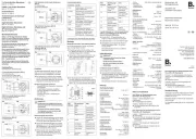
Connecting and mounting the device
< ϑ
RF
Figure 4: Electrical connection
L Outer conductor (phase)
N Neutral conductor
Load connection heating/cooling
RF Thermal resistor thermal recirculation
The N conductor must be connected to the
thermal re-circulation as a power supply, oth-
erwise large temperature variations should be
expected.
Connect the controller according to connection
diagram
(figure 4).
Mount the rocker switch (2) in the appropriate
seat opening, according to the figure.
Attach frame (3) and fix it in the correct position
with the fastening screw (5) using the centre
plate (4).
Slip the setting knob (6) on.
Commissioning
The thermo-bimetal of the controller requires
a certain amount of time to adjust itself to the
room temperature. For this reason, the switch-
ing point will deviate from the room temperature
directly after mounting. Switching point accura-
cy will only occur after approx. 1 to 2 operating
hours.
Limiting the setting range
The temperature setting range can be limited
individually using 2 setting rings on the inside of
the setting knob.
max
min
(8)
(9)
(10)
Figure 5: Setting knob from behind
(8) Setting ring, maximum temperature (red)
(9) Setting ring, minimum temperature (blue)
(10) Nose of the rotation axis
Pull the setting knob.
To set the maximum setpoint, use a suitable
pointed object to turn the red setting ring (8)
in an anticlockwise direction into the required
position.
To set the minimum setpoint, turn the blue
setting ring (9) in a clockwise direction into the
required position.
Slip the control knob on. In so doing, ensure
that the nose (10) on the rotation axis is guided
into the appropriate mounting device in the
controller.
Appendix
Technical data
Contact type Change-over contact
Temperature range 5-30 °C
Rated voltage AC 230 V
Rated current
- Heating 5 A
- Cooling 2 A
Switching capacity heating / cooling 1.1 kW
Switching difference temperature ~0.5 K
Operating temperature 0-55 °C
Degree of contamination 2
Permissible relative humidity max 95 %,
no condensation
Rated impulse voltage 4 kV
Energy class I = 1 %
Mode of action 1 C
Protection class (after complete installation
of cover) ΙΙ
Connecting terminals plug-in terminals
- rigid 1 ... 2.5 mm²
Troubleshooting
Large temperature variations in control
No thermal re-circulation, as no N conductor was
connected.
Connect N conductor
z
Produkspesifikasjoner
| Merke: | Berker |
| Kategori: | vegguttak |
| Modell: | 20291909 |
| AC-inngangsspenning: | 230 V |
| Produktfarge: | Hvit |
| Bærekraftsertifikater: | REACH, RoHS |
| Modell/Type: | Kontrollerbryter |
| Kroppsmateriale: | Plastic, Metal |
| Bærekraftsamsvar: | Ja |
Trenger du hjelp?
Hvis du trenger hjelp med Berker 20291909 still et spørsmål nedenfor, og andre brukere vil svare deg
vegguttak Berker Manualer
15 September 2025
15 September 2025

15 September 2025
15 September 2025
vegguttak Manualer
- LEDmaxx
- Vimar
- Asus
- Delta
- CyberPower
- H-Tronic
- ORNO
- Kathrein
- Sanwa
- Somfy
- Kogan
- SPC
- Osram
- Silverline
- Belkin
Nyeste vegguttak Manualer
23 Oktober 2025
18 Oktober 2025

12 Oktober 2025

5 Oktober 2025

4 Oktober 2025
4 Oktober 2025
2 Oktober 2025
1 Oktober 2025

1 Oktober 2025
1 Oktober 2025