Carel µchiller 3 Bruksanvisning
Carel
Ikke kategorisert
µchiller 3
Les nedenfor 📖 manual på norsk for Carel µchiller 3 (81 sider) i kategorien Ikke kategorisert. Denne guiden var nyttig for 9 personer og ble vurdert med 5.0 stjerner i gjennomsnitt av 5 brukere
Side 1/81
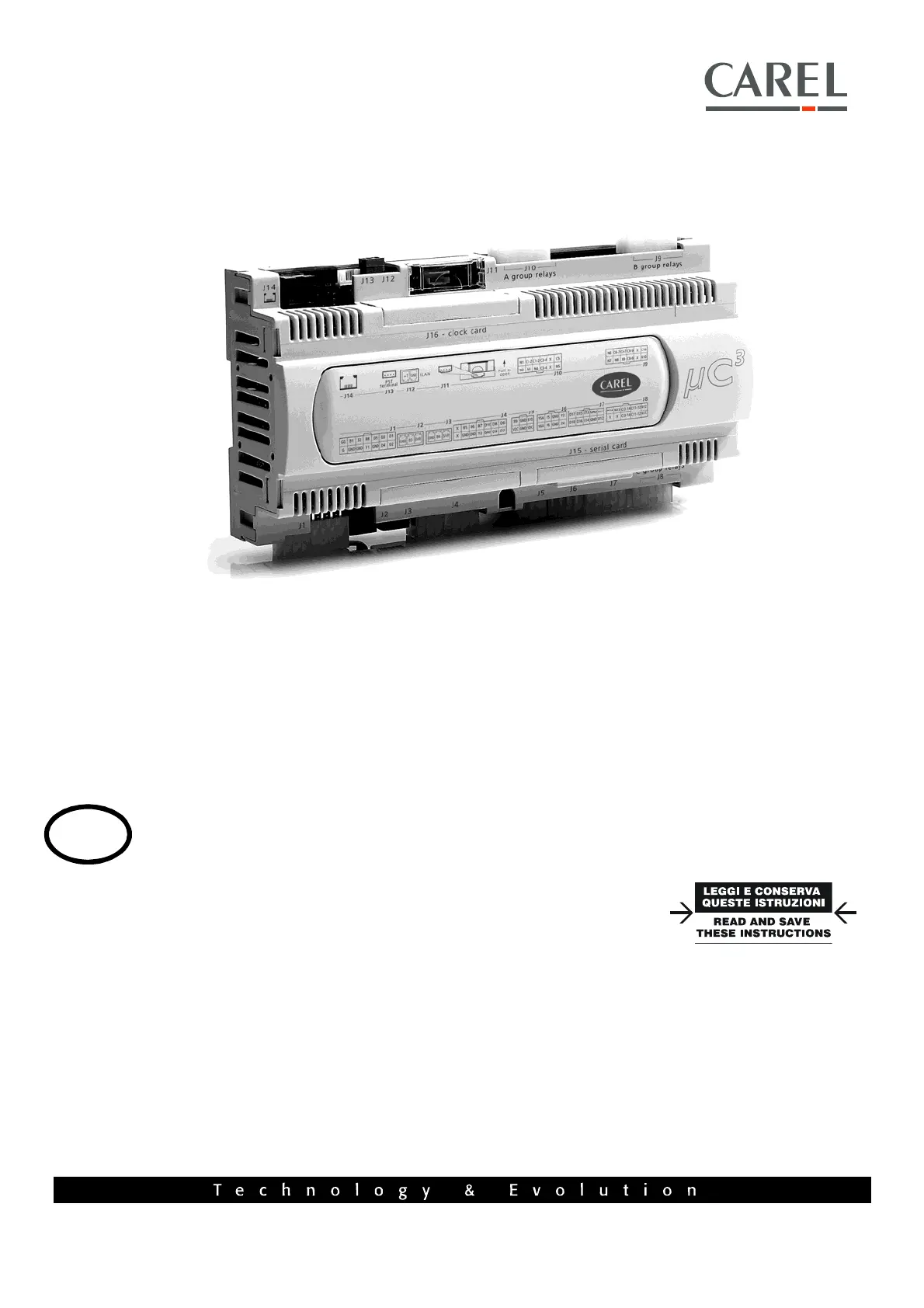
µchiller 3
ENG
User manual
Produkspesifikasjoner
| Merke: | Carel |
| Kategori: | Ikke kategorisert |
| Modell: | µchiller 3 |
Trenger du hjelp?
Hvis du trenger hjelp med Carel µchiller 3 still et spørsmål nedenfor, og andre brukere vil svare deg
Ikke kategorisert Carel Manualer
26 August 2025
26 August 2025
26 August 2025

31 Desember 2025
Ikke kategorisert Manualer
- Triplett
- Pure 100
- Estella
- DAP Audio
- Rapoo
- Dreamland
- Mafell
- Sportime
- Mebby
- Maxsa
- Hensel
- MagnaPool
- Camille Bauer
- Juice Goose
- LifeStraw
Nyeste Ikke kategorisert Manualer

23 Oktober 2025

23 Oktober 2025

23 Oktober 2025

23 Oktober 2025

23 Oktober 2025

23 Oktober 2025

23 Oktober 2025

23 Oktober 2025

23 Oktober 2025

23 Oktober 2025