Carrier Performance HRVCRSVU Bruksanvisning

Carrier Ventilator Performance HRVCRSVU

Les nedenfor 📖 manual på norsk for Carrier Performance HRVCRSVU (6 sider) i kategorien Ventilator. Denne guiden var nyttig for 3 personer og ble vurdert med 4.5 stjerner i gjennomsnitt av 2 brukere

Side 1/6
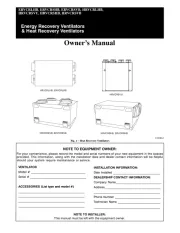
ERVCRLHB, ERVCRSHB, ERVCRSVB, HRVCRLHB,
HRVCRSVU, HRVCRSHB, HRVCRSVB
Owners Manual
Energy Recovery Ventilators
& Heat Recovery Ventilators
HRVCRLHB, ERVCRLHB
HRVCRSVU
HRVCRSVB, ERVCRSVB
HRVCRSHB, ERVCRSHB
A12308ALT
Fig. 1 Heat Recovery Ventilators
NOTE TO EQUIPMENT OWNER:
For your convenience, please record the model and serial numbers of your new equipment in the spaces
provided. This information, along with the installation data and dealer contact information will be helpful
should your system require maintenance or service.
VENTILATOR
Model # _____________________________________
Serial # ______________________________________
ACCESSORIES (List type and model #)
_____________________________________________
_____________________________________________
_____________________________________________
_____________________________________________
INSTALLATION INFORMATION:
Date Installed ________________________________
DEALERSHIP CONTACT INFORMATION:
Company Name_______________________________
Address______________________________________
_____________________________________________
Phone Number _______________________________
Technician Name _____________________________
_____________________________________________
NOTE TO INSTALLER:
This manual must be left with the equipment owner.
2
PURPOSE OF THE VENTILATION
SYSTEM
Your ventilation system is designed to provide fresh air to your
home while exhausting stale air from your home. By eliminating
accumulated pollutants and humidity, it maintains an optimum air
quality and an ideal relative humidity.
A12282
Fig. 2 Typical Installation
NOTES:
1. Typical installation shown with a forced air system, which
can also operate on its own.
2. Installation may vary according to the model number and
the position (normal or reverse) in which the unit is in-
stalled.
HEAT RECOVERY
Your ventilation system is equipped with a heat recovery core that
is designed specifically to control excess humidity and reduce
ventilation costs by recovering the heat energy from the exhausted
air, and using that same heat energy to warm the fresh air being
supplied. This heat recovery process is accomplished in such a way
that the stale air is never mixed with the fresh air.
E XAMPLE
OUTSIDE
INSIDE
Stale air to outside
Fresh air from outside
Fresh air to building
Stale air from building
A12309
Fig. 3 Heat Recovery Process
Internal Components
Unit shown in normal position Can also be installed upside down.
Position of components varies by model.
1
1
2
3
4
5
2
7
11
2
3
6
8
HRVCRSVU
HRVCRSHB
ERVCRSHB
HRVCRLHB, ERVCRLHB
A180114
Fig. 4 Component Identification
1. Filters
2. Blower
3. HRV or ERV core
4. Condensation tray
5. Fresh air supply
6. Stale air return
7. Exhaust air
8. Electronic control circuit
3
SAFETY CONSIDERATIONS
Recognize safety information. This is the safetyalert symbol
When you see this symbol on the unit and in instructions or
manuals, be alert to the potential for personal injury. Understand
these signal words; DANGER, WARNING, and CAUTION. These
words are used with the safetyalert symbol. DANGER identifies
the most serious hazards which will result in severe personal injury
or death. WARNING signifies hazards which could result in
personal injury or death. CAUTION is used to identify unsafe
practices which would result in minor personal injury or product
and property damage. NOTE is used to highlight suggestions
which will result in enhanced installation, reliability, or operation.
ELECTRICAL OPERATION HAZARD
Failure to follow this warning could result in personal injury
or death.
Before servicing system, always turn off main power to
system. Turn off accessory heater power if applicable. There
may be more than 1 disconnect switch.
!
WARNING
CUT HAZARD
Failure to follow this caution may result in personal injury.
Although special care has been taken to minimize sharp edges
in the construction of your unit, be extremely careful when
handling parts or reaching into the unit. Wear appropriate
protective clothing and gloves when working on this unit.
CAUTION
!
IMPORTANT:
Some activities create dust or vapors which may damage your unit.
You must therefore turn off and unplug your unit in the following
situations:
S Major renovation work
S Sanding (e.g. gypsum joints, etc.)
S Housing construction
S Varnishing
During very heavy snowstorms or rain with strong winds, the unit
should also be turned off to avoid problems caused by snow or rain
entering the unit, even if it is equipped with an antigust intake
hood.
CONTROLS
Integrated Control
All units are equipped with an integrated control, located on the
electrical compartment. Use the pushbutton (1) to control the unit.
The LED (2) will then show on which mode the unit is in.
NOTES:
1. The integrated control must be turned OFF to use an
optional main control.
2. If an optional auxiliary control is used, if activated, this aux-
iliary control will override the optional main control.
Refer to table below to see how to operate the unit using its
integrated control.
PRESS ON PUSH
BUTTON
LED COLOR RESULTS
Once Amber
Unit is on Low
Speed
Twice Green
Unit is on High
Speed
Three Times No Light
Unit is
OFF
2
1
WARNING
Risk of electric shock. Before performing
any maintenance or servicing, always
disconnect the unit from its power source.
AVERTISSEMENT
Danger d’électrocution. Débranchez
toujours l’appareil avant d’entreprendre
des travaux d’entretien ou de réparation.
CAUTION
Unscrew both screws to open the electrical
compartment. To completely remove, detach
from its retention wire inside.
ATTENTION
Dévisser les deux vis pour ouvrir le compartiment
électrique. Pour retirer complètement, le
détacher de son fil de rétention intérieur.
No light OFF or remote controled
Amber light LOW speed
Green ligh HIGH speed
Blinking light See User Manual
Sans lumière Arrêté ou contrôlé
par contrôle mural
Lumière ambre Basse vitesse
Lumière verte Haute vitesse
Clignotant Voir guide d’utilisation
1
2
Bottom of the unit
1
2
A12296ALT, A07260, A11210
Fig. 5 Integrated Control
Boot Sequence of Integrated Control
The unit boot sequence is similar to a personal computer boot
sequence. Each time the unit is plugged after being unplugged, or
after a power failure, the unit will perform a 30second booting
sequence before starting to operate. During the booting sequence,
the integrated control LED will light GREEN (unit set in normal
defrost) or AMBER (unit set in extended defrost) for 5 seconds,
and then will shut off for 2 seconds. After that, the LED will light
RED for the rest of the booting sequence. During this RED light
phase, the unit is checking and resetting the motorized damper
position. Once the motorized damper position completely set, the
RED light turns off and the booting sequence is done.
NOTE: No command will be taken until the unit is fully booted.
Defrost Mode
When the outside temperature is below 5_C (23_F), heat recovery
creates frost in the module. To maintain its proper operation, the
unit is programmed to defrost the recovery module. The defrost
frequency varies according to the outside temperature. Defrost lasts
610 minutes (or 10 minutes if set on “Extended Defrost”). During
the defrost cycle, the unit shifts to maximum speed and the
dampers close.
After defrosting, the unit returns to the operating mode selected by
the user.

Produkspesifikasjoner

Merke: Carrier
Kategori: Ventilator
Modell: Performance HRVCRSVU

Trenger du hjelp?

Hvis du trenger hjelp med Carrier Performance HRVCRSVU still et spørsmål nedenfor, og andre brukere vil svare deg


Ventilator Carrier Manualer

Ventilator Manualer

Nyeste Ventilator Manualer