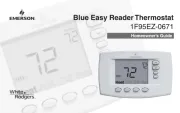
Dimplex RT 200 U Bruksanvisning
Les nedenfor 📖 manual på norsk for Dimplex RT 200 U (4 sider) i kategorien Termostat. Denne guiden var nyttig for 34 personer og ble vurdert med 4.3 stjerner i gjennomsnitt av 17.5 brukere
Side 1/4

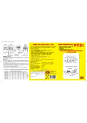
RT 200 U, RT 201 U, RT 202 U
05/08/A 1 412 734 00 (EA 08/012) FE/JD
Raumtemperaturregler Bimetall Unterputz im Flächenschalterrahmen
Bimetal room temperature controller for flush installation in a flush mounted
switch frame
Thermorégulateur à bilame pour la régulation de la température ambiante,
conçu pour l’installation encastrée avec des cadres de recouvrement plats
Regulator temperatury pomieszczenia bimetal podtynkowy w ramie powierzchownego
przełącznika
Sicherheitshinweis!
Dieses Gerät darf nur durch eine Elektrofachkraft geöffnet und gemäß dem
entsprechenden Schaltbild im Gehäusedeckel / auf dem Gehäuse / in der Bedie-
nungsanleitung installiert werden. Dabei sind die bestehenden Sicherheitsvor-
schriften zu beachten. Der Betrieb in der Nähe von Geräten, welcheAchtung!
nicht den EMV-Richtlinien entsprechen, kann zur Beeinflussung der Gerätefunk-
tionen führen. Nach der Installation ist der Betreiber, durch die ausführende
Installationsfirma, in die Funktion und Bedienung der Regelung einzuweisen.
Die Bedienungsanleitung muss für Bedien- und Wartungspersonal an frei zu-
gänglicher Stelle aufbewahrt werden.
1. Anwendung
Dieser Raumtemperaturregler wurde speziell für die Regelung oder Überwa-
chung von Temperaturen in Büros, Wohnräumen und Hotels entwickelt und ist
geeignet für alle Heizungsarten. Bei elektrischen Fußbodenheizungen ist darauf
zu achten, dass die Leistung der Heizung auch bei Dauerbetrieb den Estrich
nicht überhitzen kann. Bei Warmwasserheizungen sind auf den Heizausgang
max. 10 stromlos geschlossene Ventile anzuschließen. Gegebenenfalls benötigte
Temperaturbegrenzungen müssen zusätzlich installiert werden. Für andere, vom
Hersteller nicht vorherzusehende Einsatzgebiete, sind die dort gültigen Sicher-
heitsvorschriften zu beachten. Eignung hierfür siehe Punkt 7. Gewährleistung.
2. Funktionen
Safety Instructions!
This device should be opened only by an electrical expert and installed in accor-
dance with the corresponding circuit diagram in the E housing lid / on the housing
/ in the operating instructions. Moreover, the existing safety regulations are to be
observed. Note! Operating the equipment in the vicinity of equipment, which does
not comply with electromagnetic compatibility guidelines, may affect the functio-
ning of the equipment. After the installation, the operator is to be oriented by the
installing company in the functioning and operation of the control system. The
operating instructions must be kept in a place freely accessible to operating and
maintenance personnel.
1. Application
This temperature controller has been specially devised for the control and
supervision of temperatures in offices, living spaces and hotels and is suited for
the control of all types of heating systems. With electric floor heating systems
care must be taken to ensure that the performance of the controlled system
cannot, even if the system is operated continuously, result in an overheating of
the pavement. With hot water heating systems, no more than 10 normally
closed valves must be used. Where applicable, temperature limiters need to be
installed in addition. Regarding other applications not to be foreseen by the
manufacturer of this device, the safety standards these applications need to be
followed and adhered to. Regarding the aptitude of the device for any such
application, please refer to section 7. herein.
D GB
2. Functioning
The room temperature controller described herein is equipped with an internal bi-
metal sensor that captures the currently existing room temperature. The device
controls the related heating or cooling system in accordance with the adjusted
set value. The different controller models have been provided with different
equip
ment, such as with an ON/OFF switch, a red “heating” lamp (type RT 201 U)
or with
a red “additional heating ON/OFF” lamp and corresponding switch (type
RT 202 U).
2.1 Thermal recirculation
As, during the heating or cooling procedure, the controller usually captures the
actually prevailing room temperature at a rather late point, a thermal recirculation
has been realised with the device that enables to excite it early enough with the
consequence that a very precise switching difference can be attained.
2.2 Suppression of the setting range
The setting elements (pins) located underneath of the knob enable to delimit the
setting range mechanically (see sections 3. and 6.).
2.3 ECO mode (night temperature decrease mode)
With all controller models that enable to operate in ECO mode (indicated by the
clock symbol shown in the connection diagram), the room temperature is decrea-
sed by approx. 4K when connecting the 230V~ power supply to the terminal .
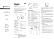
3. Installation / Montage 3. Mounting / Installation
Je nach Gerätetyp oder Verpackungsgröße, wird das Gerät entweder geschlos-
sen oder der schnelleren Montage wegen geöffnet ausgeliefert. Das Gerät ist
mittels Zwischenrahmen der Schalterhersteller nach DIN 49075 in nahezu alle
Schalterprogramme integrierbar. Bei Mehrfachrahmen ist der Regler immer an
unterster Stelle zu montieren. Der Regler ist zur Montage in die UP-Dose be-
stimmt und darf nicht direkt Wärme- oder Kältequellen ausgesetzt werden. Es
ist darauf zu achten, dass der Regler auch rückseitig keiner Fremderwärmung
oder -kühlung, z.B. bei Hohlwänden durch Zugluft oder Steigleitungen ausge-
setzt wird.
Zum Öffnen des Reglers ist die Schraube nach Abziehen des Einstellknopfes zu
lösen und die Reglerkappe inklusive Rahmen abzunehmen. Nach elektrischem
Anschluss und Montage in die UP-Dose, ist der Regler in umgekehrter Reihen-
folge wieder zu schließen (siehe Punkt 6.).
Um den Einstellbereich Einzuengen, wird der sich unter dem Einstellknopf be-
findliche Stift abgezogen und die Einstellfahnen verstellt (rot für maximal und
blau für minimal mögliche Einstellung). Anschließend wird der Stift wieder ein-
gesteckt und somit die Begrenzungen arretiert (siehe Punkt 6.).
The device is, depending on the type version of the device or the size of the
package used for it, either delivered in closed or, in order to facilitate its fast
installation, also in opened condition. The device suits for the integration into
almost all DIN 49075 compliant intermediate frames that form part of the diffe-
rent frame lines offered by different producers. If using multiple frames, the
controller must always be mounted in the lowest position. The controller is
determined for installation on an UP box and must not directly be exposed to
any heat or cold sources whatsoever. Also care must be taken to ensure that it
is not exposed to the influence of heat or cold sources that warm or cool the
device at its back (through air flows in cavity walls or the temperatures radiated
by ascending pipelines, f. ex.).
To open the controller, remove the adjusting knob first, then loosen the screw
and remove the controller cap including the frame. After its electrical connec-
tion and installation in the UP box, the closing of the controller takes place in
inverse order (see section 6.).
The setting pins located underneath of the adjusting knob enable to delimit the
setting range of the controller mechanically. To enable this, the adjusting knob
must be removed by pulling it off and, after the adjustment of the related pins
(end stops, red for max. and blue for min. setting) be put on again in order to
lock the limitations (see section 6.).
Der Raumtemperaturregler erfasst mit einem innenliegenden Bimetallfühler die
Raumtemperatur und regelt entsprechend dem eingestellten Sollwert. Die
einzelnen Reglertypen unterscheiden sich durch die Ausstattung, wie Schalter
„Ein / Aus“ und Lampe rot „Heizen“ (Typ RT 201 U), Schalter und Lampe rot
„Ein / Aus Zusatzheizung“ (Typ RT 202 U)
2.1 Thermische Rückführung
Da während des Heiz- oder Kühlvorgangs der Regler die Raumtemperatur erst
relativ spät erfasst, wird mittels einer thermischen Rückführung der Regler
rechtzeitig zum Ausschalten angeregt und so eine sehr genaue Schaltdifferenz
erreicht.
2.2 Bereichseinengung
Mittels der sich unter dem Knopf befindlichen Einstellfahnen kann der Einstell-
bereich mechanisch begrenzt werden. (siehe Punkt 3. und 6.).
2.3 ECO-Betrieb (Nachtabsenkung)
Bei Reglern mit ECO-Betrieb (Uhrensymbol im Anschluss-Schaltbild) wird bei
Beschalten der Klemme mit 230 V~ auf eine um ca. 4K geringere Tempera-
tur geregelt.
Produkspesifikasjoner
| Merke: | Dimplex |
| Kategori: | Termostat |
| Modell: | RT 200 U |
Trenger du hjelp?
Hvis du trenger hjelp med Dimplex RT 200 U still et spørsmål nedenfor, og andre brukere vil svare deg
Termostat Dimplex Manualer

27 Oktober 2024

27 Oktober 2024

27 Oktober 2024

18 Oktober 2024
Termostat Manualer
- Itho
- Johnson Control
- Hive
- Plieger
- Hoffman
- Velleman
- Webasto
- Danfoss
- TP Link
- Boneco
- Helios (Amfra)
- Tellur
- Oregon Scientific
- Vemer
- Seitron
Nyeste Termostat Manualer
19 Oktober 2025
19 Oktober 2025
9 Oktober 2025
8 Oktober 2025
6 Oktober 2025
6 Oktober 2025
6 Oktober 2025
24 September 2025
24 September 2025
24 September 2025