Emerson 1F85U-22NP Bruksanvisning
Les nedenfor 📖 manual på norsk for Emerson 1F85U-22NP (12 sider) i kategorien Termostat. Denne guiden var nyttig for 48 personer og ble vurdert med 5.0 stjerner i gjennomsnitt av 24.5 brukere
Side 1/12
PART NO. 37-7572B-EN
1535
1F85U-22NP (Non-Programmable)
Installation and Operating Instructions
80 Series
TM
Universal Thermostat
Battery Powered or Hardwired with Common
white-rodgers.com
emersonclimate.com
Thermostat Applications
Maximum
Stages
Heat/ Cool
Conventional Gas, Oil, Electric
(mV and 24V), Heat only, Cool only or
Heat/Cool Systems
2/2
Heat Pump (Air Source or Geothermal)
with Aux. Heat
2/1
Thermostat Installation
2-4
Wiring
2
Installer Menu
3-4
Test Equipment
4
Using the Thermostat
5-7
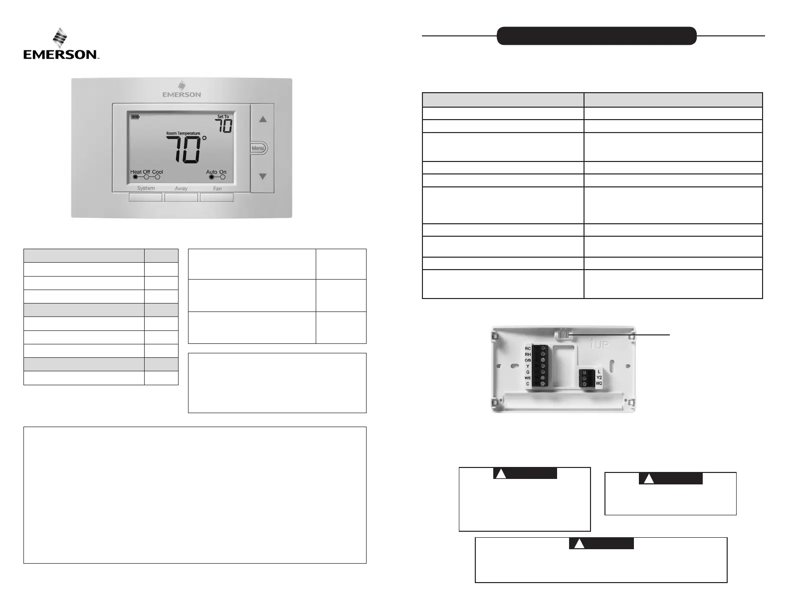
Thermostat Overview
5
User Menu
6
Thermostat Operation
6
Troubleshooting
7-8
Homeowner Help Line
8
INDEX
MERCURY NOTICE: This product does not contain
mercury. However, this product may replace a product
that contains mercury. Mercury and products containing
mercury must not be discarded in household trash.
Refer to www.thermostat-recycle.org for information
on disposing of products containing mercury.
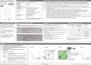
Electrical Rating:
Battery Power ..................................... mV to 30 VAC, NEC Class II, 50/60 Hz
Input-Hardwire .................................... 20 to 30 VAC, NEC Class II, 50/60 Hz
Terminal Load .......................................... 1.5 A per terminal, 2.5A maximum all terminals combined
Setpoint Range ........................................ 45° to 99° F (7° to 37° C)
Rated Dierentials (@ 6°F/ Hr): Fast Med Slow
Heat (Conventional Gas / Oil / Elect) ..... 0.5°F 0.75°F 1.9°F
Cool (Central Air) ................................. 0.9°F 1.2°F 1.7°F
Heat Pump (Heat and Cool) ................ 0.9°F 1.2°F 1.7°F
Heat Pump Aux. .................................. 0.5°F 0.75°F 1.9°F
Operating Ambient .................................. 32°F to +105°F (0° to +41°C)
Display Temperature Range ....................... 32°F to +99°F (0 to 37°C)
Operating Humidity ................................. 90% non-condensing maximum
Shipping Temperature Range ................... -20°F to + 150°F (-29° to +65°C)
Thermostat Dimensions ........................... 3-3/4” H x 6” W x 1-1/8” D
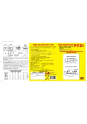
SPECIFICATIONS
Optional Accessory: Wall Cover-Up Plate F61-2663, 6-3/4” W x 4-1/2” H
Terminal Designations Terminal Function
RC
Power (24V) - Cooling
RH
Power (24V) - Heating
O/B
6 (not shown) - 3 wire zone valve
Reversing Valve or output for 3 wire zone valves
Congurable as “O” or “B” Reversing Valve or 3 wire
zone heat (power close)
Y
1st Stage Compressor (conventional or heat pump)
G Fan Relay
W/E
1st Stage Heat (conventional);
1st Stage Auxiliary Heat (heat pump)
Can operate as Emergency Heat only
(See Installer Menu #15)
C
Common wire for 24V (optional with batteries)
L
Heat Pump Malfunction / Diagnostic terminal
(input signal requires common)
Y2 2nd Stage compressor (conventional only)
W2
2nd Stage Heat (Conventional)
Can operate as 1st Stage Auxiliary Heat
(See Installer Menu #15)
WIRING
Refer to equipment manufacturer’s instructions for specic system wiring information. After wiring, see
INSTALLER MENU for proper thermostat conguration. Wiring table shown are for typical systems and
describe the thermostat terminal functions. Wiring will change when dedicated emergency heat is on
(See Installer Menu #15).
THERMOSTAT INSTALLATION
Precautions
• Do not exceed the specication ratings.
• All wiring must conform to local and national electrical codes and ordinances.
• This control is a precision instrument, and should be handled carefully. Rough handling or
distorting components could cause the control to malfunction.
WARNING
!
Do not use on circuits exceeding specied voltage.
Higher voltage will damage control and could
cause shock or re hazard.
Do not short out terminals on gas valve or primary
control to test. Short or incorrect wiring will burn
out thermostat and could cause personal injury
and/or property damage.
CAUTION
!
To prevent electrical shock and/or equipment
damage, disconnect electrical power to system,
at main fuse or circuit breaker box,until
installation is complete.
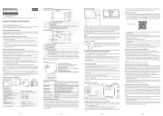
Leveling Thermostat
Leveling is for appearance only and
will not aect thermostat operation.
CAUTION
!
To prevent compressor and/or property damage, if the outdoor temperature is below 50°F,
DO NOT operate the cooling system.
Do not allow the compressor to run unless the compressor oil heaters have been operational
for 6 hours and the system has not been operational for at least 5 minutes.
2
Produkspesifikasjoner
| Merke: | Emerson |
| Kategori: | Termostat |
| Modell: | 1F85U-22NP |
Trenger du hjelp?
Hvis du trenger hjelp med Emerson 1F85U-22NP still et spørsmål nedenfor, og andre brukere vil svare deg
Termostat Emerson Manualer
6 Oktober 2025
6 Oktober 2025
6 Oktober 2025

27 Oktober 2024

27 Oktober 2024

27 Oktober 2024

27 Oktober 2024

27 Oktober 2024

27 Oktober 2024

18 Oktober 2024
Termostat Manualer
- Hunter
- Easy Timer
- Yokis
- Warmup
- Viessmann
- Amfra
- STI
- EQ-3
- Econo-Heat
- AWB
- Honeywell
- Hager
- Eurotronic
- Emmeti
- VDH
Nyeste Termostat Manualer
19 Oktober 2025
19 Oktober 2025

9 Oktober 2025
8 Oktober 2025
24 September 2025

24 September 2025
24 September 2025

15 September 2025

12 September 2025
12 September 2025