Fluke 700PTP-1 Bruksanvisning
Les nedenfor 📖 manual på norsk for Fluke 700PTP-1 (2 sider) i kategorien pumpe. Denne guiden var nyttig for 10 personer og ble vurdert med 4.9 stjerner i gjennomsnitt av 5.5 brukere
Side 1/2
PN 2811824
April 2007
©2007 Fluke Corporation. All rights reserved. Printed in U.S.A.
All product names are trademarks of their respective companies.
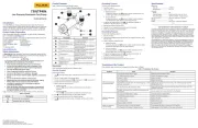
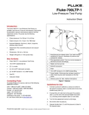
Pump Valve Assembly Cleaning Instructions
Occasionally, the 700PTP-1 may not work properly due to contamination of
the internal valve assembly. Use the following procedure to clean the valve
assembly. If the procedure does not fix the problem, a repair kit (part
number 2812587) may be ordered.
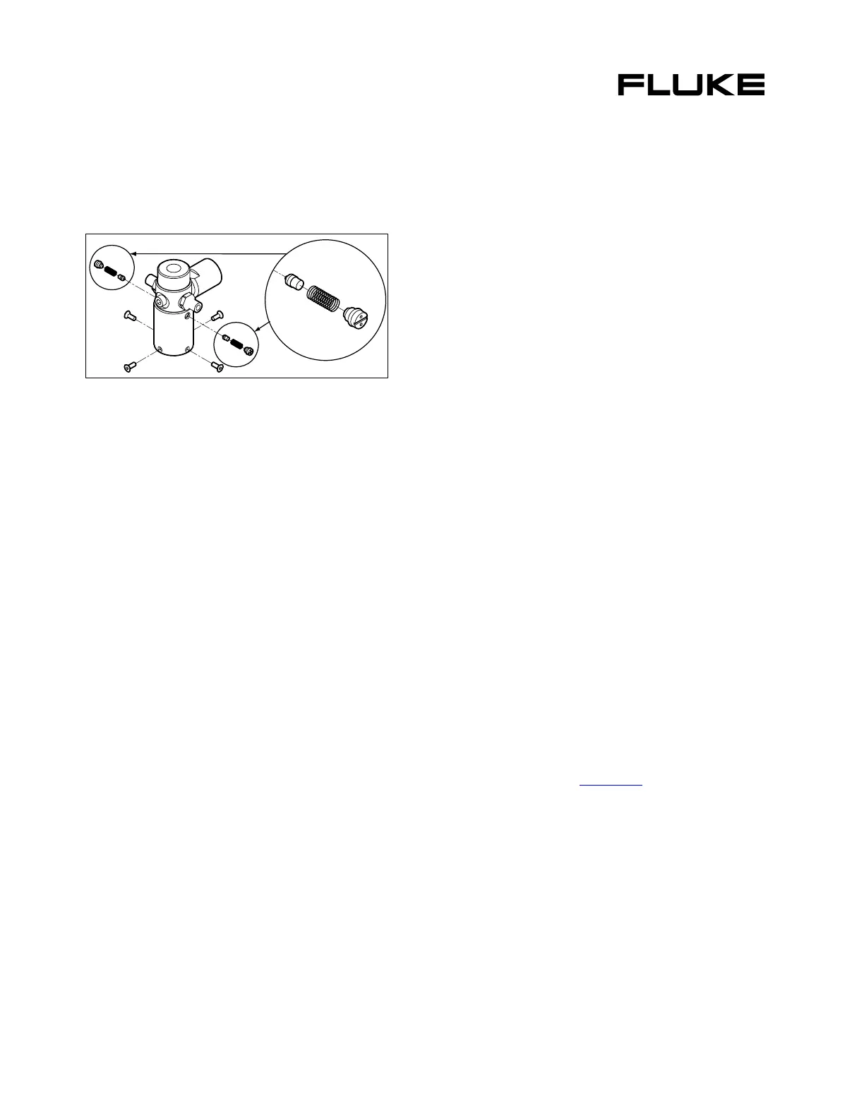
1. Using a small screwdriver, remove the 2 valve retention caps located
on opposite sides of the pump below the pressure/vacuum switch.
2. Gently remove the spring and o-ring assembly. Take care when
removing check valve as it contains several small components. See
Figure 3.
euz03f.eps
Figure 3. Cleaning the Valve Assembly
3. Set aside the valve assemblies and clean out the valve body using a
cotton swab soaked in isopropyl alcohol.
4. Repeat the process several times using a new swab until clean.
5. Operate the pump handles several times and recheck for
contamination.
6. Clean the o-ring assembly and the o-ring on the retention caps with
isopropyl alcohol and inspect the o-rings closely for any damage or
excessive wear. Replacements are included in the repair kit.
7. Inspect the springs for wear or loss of tension. They should be
approximately 8.6 mm long in the relaxed state. If shorter, they may
provide sufficient sealing tension. Replace if needed.
8. Once all parts have been cleaned and inspected, reinstall the o-ring
and spring assembly into the valve body.
9. Reinstall the retention caps and gently tighten each cap.
10. Seal the output port and operate the pump to at least 50 % of capacity.
11. Release the pressure and repeat several times to ensure that the
o-rings seat properly.
Replacement Parts
Hose assembly, Fluke PN 2815714
Rebuild kit, Fluke PN 2812587
Bleed Valve Assembly (Needle) Fluke PN 2844329
LIMITED WARRANTY AND LIMITATION OF LIABILITY
This Fluke product will be free from defects in material and workmanship for one year
from the date of purchase. This warranty does not cover fuses, disposable batteries,
or damage from accident, neglect, misuse, alteration, contamination, or abnormal
conditions of operation or handling. Resellers are not authorized to extend any other
warranty on Fluke’s behalf. To obtain service during the warranty period, contact your
nearest Fluke authorized service center to obtain return authorization information,
then send the product to that Service Center with a description of the problem.
THIS WARRANTY IS YOUR ONLY REMEDY. NO OTHER WARRANTIES, SUCH AS
FITNESS FOR A PARTICULAR PURPOSE, ARE EXPRESSED OR IMPLIED. FLUKE IS
NOT LIABLE FOR ANY SPECIAL, INDIRECT, INCIDENTAL OR CONSEQUENTIAL
DAMAGES OR LOSSES, ARISING FROM ANY CAUSE OR THEORY. Since some
states or countries do not allow the exclusion or limitation of an implied warranty or
of incidental or consequential damages, this limitation of liability may not apply to
you.
Fluke Corporation
P.O. Box 9090
Everett, WA 98206-9090
U.S.A.
Fluke Europe B.V.
P.O. Box 1186
5602 BD Eindhoven
The Netherlands
11/99
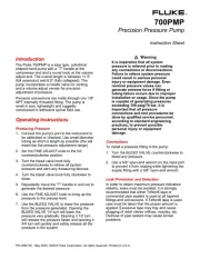
Introduction
The Fluke-700PTP-1 Pneumatic Test Pump (hereafter called the “pump”) is
a handheld device that develops precise pressure and vacuum. The pump
has the following specifications:
• Pressure to 40 bar (600 psi)
• Vacuum to -0.96 bar (-13.9 psi)
• Wetted materials: aluminum, silicon, neoprene, stainless steel,
Buna-N
• Weight: 1.03 lb (467 g)
• Dimensions: length 8.7 in (220 mm), width 4.8 in (122 mm), depth
3.5 in (89 mm)
Box Contents
• 700PTP-1 Pneumatic Test Pump
• 1/4 in NPT male to 1/4 in BSP female
• 1 m hose
• (2) 1/8 in NPT male quick connects
• 1/8 NPT female to 1/4 in BSP female
• Seal Kit
• Instruction Sheet
Contacting Fluke
To contact Fluke or for service, call one of the following telephone numbers:
USA: 1-888-44-FLUKE (1-888-443-5853)
Canada: 1-800-36-FLUKE (1-800-363-5853)
Europe: +31 402-675-200
Japan: +81-3-3434-0181
Singapore: +65-738-5655
Anywhere in the world: +1-425-446-5500
Or, visit Fluke's Web site at www.fluke.com
.
®
Fluke-700PTP-1
Pneumatic Test Pump
Instruction Sheet
Produkspesifikasjoner
| Merke: | Fluke |
| Kategori: | pumpe |
| Modell: | 700PTP-1 |
| Produkttype: | Pneumatisk testpumpe |
| Vekt: | 467 g |
| Bredde: | 122 mm |
| Dybde: | 220 mm |
| Høyde: | 89 mm |
| Bruksanvisning: | Ja |
| Materiale: | Aluminium, Neoprene, Silicone, Stainless steel |
| Merkekompatibilitet: | Fluke |
| Maks driftspress: | 40 stang |
| Slange inkludert: | Ja |
| Lufttrykk (maks): | - stang |
| Pakninger inkludert: | Ja |
Trenger du hjelp?
Hvis du trenger hjelp med Fluke 700PTP-1 still et spørsmål nedenfor, og andre brukere vil svare deg
pumpe Fluke Manualer
30 August 2025
30 August 2025
30 August 2025
29 August 2025
29 August 2025
29 August 2025
29 August 2025
29 August 2025
29 August 2025
29 August 2025
pumpe Manualer
- Eurom
- Grundfos
- POLARIS
- SKS
- Oase
- Ryobi
- Sauermann
- T.I.P.
- Einhell
- Zoeller
- Chapin
- Eheim
- Parkside
- Ozito
- Draper
Nyeste pumpe Manualer
6 Oktober 2025
6 Oktober 2025
6 Oktober 2025
6 Oktober 2025
6 Oktober 2025
5 Oktober 2025

5 Oktober 2025
5 Oktober 2025
5 Oktober 2025

5 Oktober 2025