Fusion CAB000541 Bruksanvisning
Fusion
Ikke kategorisert
CAB000541
Les nedenfor 📖 manual på norsk for Fusion CAB000541 (6 sider) i kategorien Ikke kategorisert. Denne guiden var nyttig for 11 personer og ble vurdert med 3.8 stjerner i gjennomsnitt av 6 brukere
Side 1/6
Maretron NMEA 2000
®
Network Installation Guide
Installing an NMEA 2000
®
Network
Installing an NMEA 2000
®
network consists of interconnecting
NMEA 2000
®
electronic devices using plug-and-play
cables and connectors. The following pages provide a brief
description of how to set up a NMEA 2000
®
network using
five basic steps:
1. Cable and Connector Network Basics
2. Installing Terminators
3. Supplying Power
4. Grounding the Network
5. Checking the Network
Please note that this installation guide contains a brief
description of the basic concepts of installing an NMEA
2000® network and Maretron suggests that you consult
a trained professional for any installation. You can learn
more about installing NMEA 2000
®
networks by contacting
the National Marine Electronics Association (NMEA) at
www.nmea.org and consulting the following documents:
• NMEA 2000
®
Standard for Serial-Data Networking of
Marine Electronic Devices
• NMEA Installation Standards
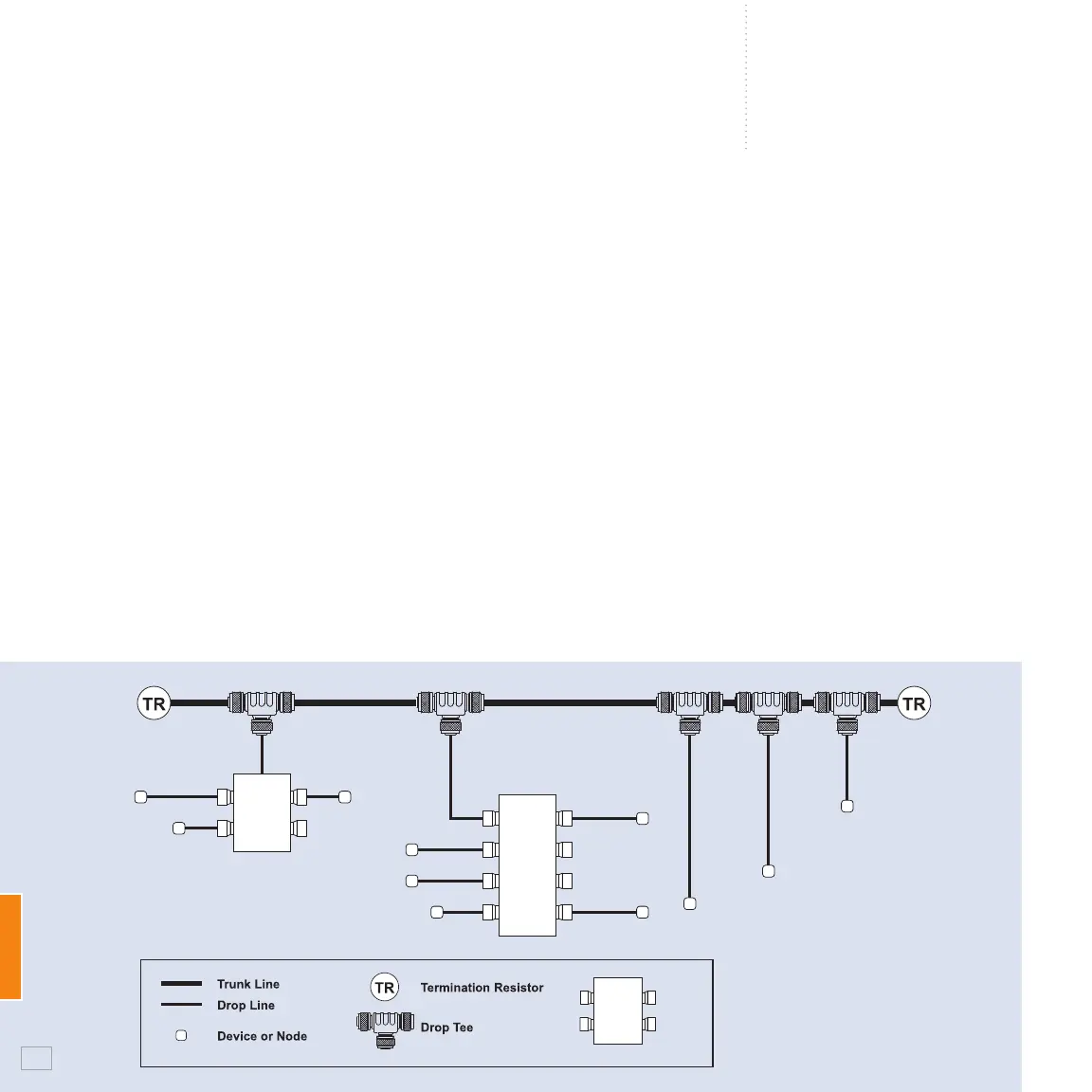
1. Cable and Connector Network Basics
1.1 Network Topology
The NMEA 2000
®
cable system uses a trunk (sometimes
referred to as the backbone) and drop line topology as
shown in Figure 1.
The NMEA 2000
®
cable system includes five wires within a
single waterproof cable: two signal wires, power and ground
wires, and a drain wire. The drain wire shields the signal, power,
and ground wires from external Radio Frequency Interference
(RFI) and helps reduce RFI emission from the cable.
You can connect devices using one of three cable options:
Mini - This is commonly used for the trunk line on the network
because of its greater current carrying capacity (8 amps) as
Figure 1
NMEA 2000
®
Network Topology
Multi
Port
Box
110
Produkspesifikasjoner
| Merke: | Fusion |
| Kategori: | Ikke kategorisert |
| Modell: | CAB000541 |
Trenger du hjelp?
Hvis du trenger hjelp med Fusion CAB000541 still et spørsmål nedenfor, og andre brukere vil svare deg
Ikke kategorisert Fusion Manualer
3 September 2025
3 September 2025
3 September 2025

3 September 2025
2 September 2025
2 September 2025
2 September 2025
2 September 2025
2 September 2025

2 September 2025
Ikke kategorisert Manualer
- Steinel
- Catlink
- Goodway
- SureFire
- APSystems
- Sauermann
- Singer
- Karma
- Brändi
- Moultrie
- MoFi
- Novation
- Generac
- Sodapop
- A-Designs
Nyeste Ikke kategorisert Manualer

23 Oktober 2025

23 Oktober 2025

23 Oktober 2025

23 Oktober 2025

23 Oktober 2025

23 Oktober 2025

23 Oktober 2025

23 Oktober 2025

23 Oktober 2025

23 Oktober 2025