Gossen Metrawatt SECULIFE ST BASE IQ Bruksanvisning
Gossen Metrawatt
måleinstrument
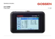
SECULIFE ST BASE IQ
Les nedenfor 📖 manual på norsk for Gossen Metrawatt SECULIFE ST BASE IQ (96 sider) i kategorien måleinstrument. Denne guiden var nyttig for 17 personer og ble vurdert med 4.9 stjerner i gjennomsnitt av 9 brukere
Side 1/96
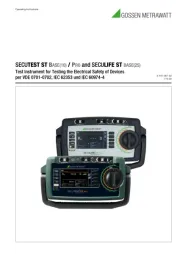
Operating Instructions
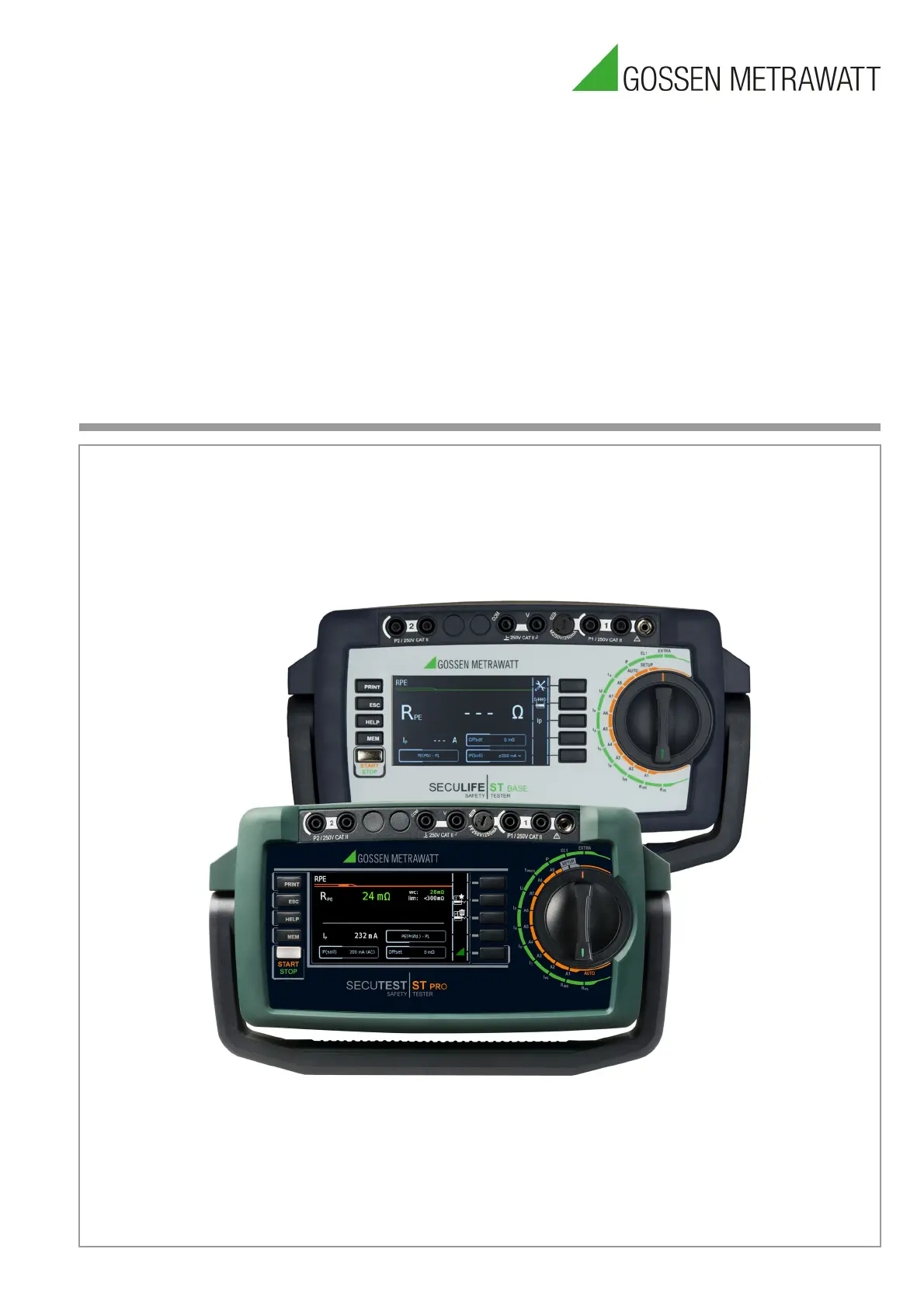
SECUTESTST BASE(10) / PRO and SECULIFE STBASE(25)
Test Instrument for Testing the Electrical Safety of Devices
per VDE 0701-0702, IEC 62353 und IEC 60974-4
3-447-067-03
1/10.20
Produkspesifikasjoner
| Merke: | Gossen Metrawatt |
| Kategori: | måleinstrument |
| Modell: | SECULIFE ST BASE IQ |
Trenger du hjelp?
Hvis du trenger hjelp med Gossen Metrawatt SECULIFE ST BASE IQ still et spørsmål nedenfor, og andre brukere vil svare deg
måleinstrument Gossen Metrawatt Manualer
29 August 2025
2 August 2025
2 August 2025
2 August 2025
2 August 2025
måleinstrument Manualer
- H-Tronic
- Greisinger
- Steinberg
- Dasqua
- AS - Schwabe
- Carrier
- TFA
- Grundfos
- Sanwa
- Vemer
- MGL Avionics
- Trotec
- SRS
- Extech
- True Blue Power
Nyeste måleinstrument Manualer
21 Oktober 2025
21 Oktober 2025
20 Oktober 2025
19 Oktober 2025
16 Oktober 2025
16 Oktober 2025
15 Oktober 2025
15 Oktober 2025
15 Oktober 2025
13 Oktober 2025