Growatt SYN 100-XH-30 Bruksanvisning
Les nedenfor 📖 manual på norsk for Growatt SYN 100-XH-30 (4 sider) i kategorien kontroll. Denne guiden var nyttig for 9 personer og ble vurdert med 4.9 stjerner i gjennomsnitt av 5 brukere
Side 1/4
1 2 3 4
5 6
7
2
1
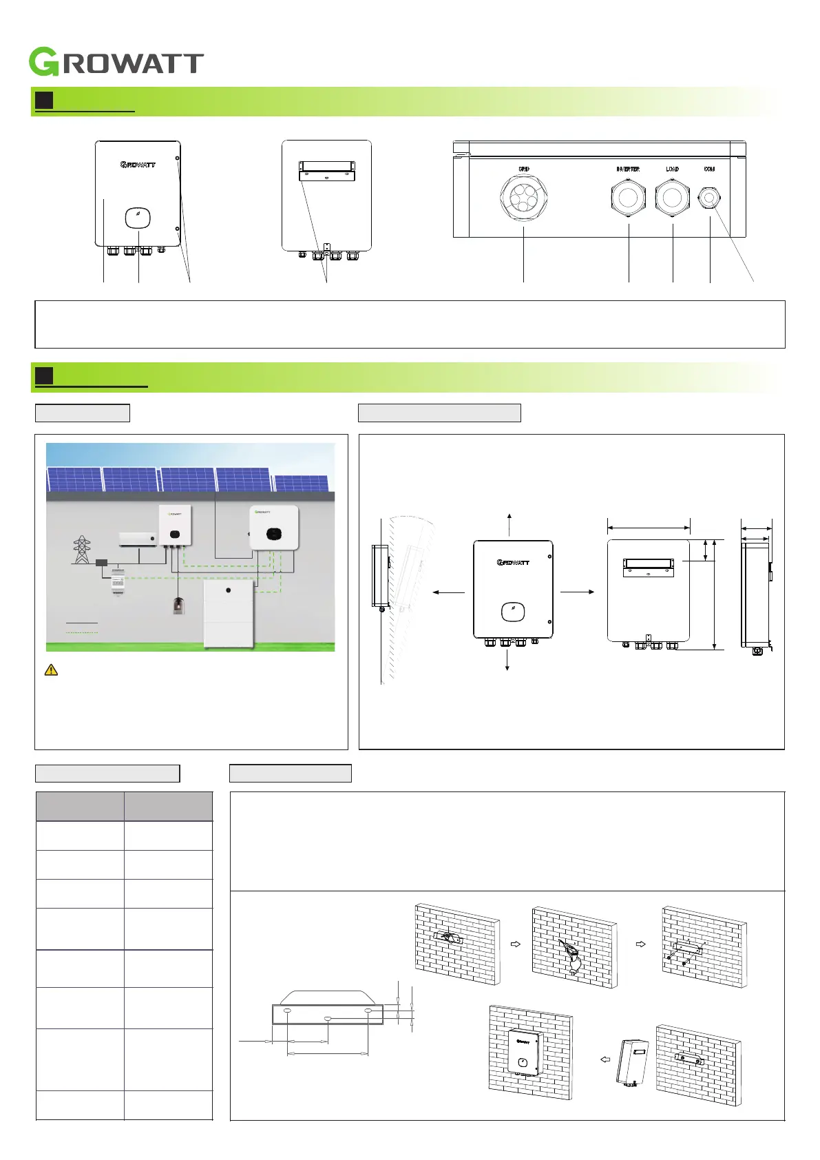
Screw torque
Power grid terminals
26.5 to 31 in*lbs
Ground terminal
13 in*lbs
3
SYN 100-XH-30
Grid
Grid
PE
N
L3 L2 L1
L1
L2
L3
N
PE
L1 L2 L3 N L 1 L2 L3 N L1 L2 L3 N L 1 L2 L3 N
GRID
BYPASS
INVERTER
LOAD
2.4 Required tools
No.
Name
Size
No.
Name
Size
1
Flat-blade
screwdriver
Φ2&5 mm
2
Hammer
/
3
Allen wrench
Φ5 mm
4
Phillips
screwdriver
Φ5 mm
5
Electric drill
Φ6 mm
6
Wire stripper
/
7
Pliers
/
3.
Recommended cable specifications
Please prepare suitable cables for the connection of the SYN box following the recommended specifications, and the stripped length of the
cables is 10 mm.
Cable
Cable outer
diameter
Cable length
Grid input cable
4-6 AWG
10 m
Inverter input cable
6-8 AWG
20 m
Load output cable
6-8 AWG
20 m
Communication cable
22-26 AWG
20 m
4-6 AWG
10 m
L
10 mm
10 m
4-6 AWG
4-6 AWG
N
10 mm
10 m
PE
10 mm
Grid AC cable
20 m
6-8 AWG
L
10 mm
20 m
6-8 AWG
6-8 AWG
N
10 mm
20 m
PE
10 mm
Load and lnverter AC cable
20 m
20m
22-26 AWG
22-26 AWG
L
10 mm
N
10 mm
Communication cable
3.1 Wiring instructions
3.1.1 Connecting SYN 100-XH-30 to the Grid
1. Remove the two screws on the upper cover of the SYN 100-XH-30 to open the upper cover, and do
not remove the cover inside the machine.
2. Twist the plastic cover printed with "Grid" counterclockwise, remove the five waterproof plugs, and
reserve five holes.
3. Route the five power grid cables (L1/L2/L3/N/PE) through the five holes and connect them to the
power grid input terminals and the ground copper bar. Screw torques for tightening the power grid
terminals and ground terminals are shown in the following table.
4. Finally, fasten the plastic cover clockwise. The wiring method is shown in Figure 3.
Note: PE cables need to be crimped with the O-type
terminal in the accessory bag, as shown in
Figure 2.
Connecting to the Grid
3.1.2 Connecting SYN 100-XH-30 to the Inverter
When connecting the SYN 100-XH-30 to the XH Inverter, you need to connect the AC power cables and the communication cables.
1.
2.
SYN 100-XH-30 Quick Guide
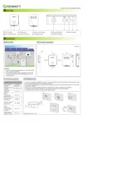
Overview
Installation
System overview
2.2 Installation requirements
2.1 Electrical parameters
1. Choose a suitable installation position. The SYN 100-XH-30 can be mounted on a solid wall, a stud
frame or a pole and keep it free from direct sunlight.
2. To ensure heat dissipation, please maintain at least a 300 mm clearance between the SYN 100-XH-
30 and other objects.
3. Place the mounting bracket against the wall/pole and mark the drilling hole positions.
4. Drill holes and mount the bracket. Ensure that the bracket is securely installed.
5. Install the SYN 100-XH-30 onto the mounting bracket.
1 2 3 4 5
6
7 8 9
10KTL
Normal Loads
Critical Loads
Inverter
Battery
Meter
Backup
Box
CT
Communication cable
Power cable
≤15°
≥300
≥300
≥300
≥500
21.1
5.3
28.1
365.0
486.3
92.5
8.0
7.1
134.7
120.2
Note:
1. The critical load power depends on the power rating
of the inverter and battery.
2. The off-grid function is only available when the XH
inverter is paired with the APX battery system and
the backup box.
Model name
SYN 100-XH-30
Nominal grid
voltage
3W/N/PE
230/400 a.c.V
Range of grid
voltage
312~485 a.c.V
Max. grid
current
125 a.c.A
Max.
continuous
grid current
90 a.c.A
Nominal grid
frequency
50/60Hz
Range of grid
frequency
45~65Hz
Max.
continuous
inverter input
current
58 a.c.A
Max. backup
output current
58 a.c.A
2.3 Installation steps
(1) Front panel
(2) LED indicator
(3) Screw for front panel
(4) Mounting bracket
(9) Waterproof plugs
(5)Grid wiring port
(6) Inverter wiring port
(7) Load wiring port
(8) COM wiring port
Dimensions (Unit: mm)
Unit: mm
30.5
82
164
12
16
Produkspesifikasjoner
| Merke: | Growatt |
| Kategori: | kontroll |
| Modell: | SYN 100-XH-30 |
Trenger du hjelp?
Hvis du trenger hjelp med Growatt SYN 100-XH-30 still et spørsmål nedenfor, og andre brukere vil svare deg
kontroll Growatt Manualer
5 September 2025
kontroll Manualer
- Alfatron
- Tripp Lite
- Homematic IP
- Mackie
- Spektrum
- Icy Box
- Behringer
- Razer
- Aruba
- Fusion
- Turtle Beach
- Zebra
- Schneider
- Phoenix Contact
- DataVideo
Nyeste kontroll Manualer

18 Oktober 2025
16 Oktober 2025

16 Oktober 2025
15 Oktober 2025

10 Oktober 2025

10 Oktober 2025

10 Oktober 2025


9 Oktober 2025