Hager TXC518 Bruksanvisning
Hager
Bevegelsesdetektor
TXC518
Les nedenfor 📖 manual på norsk for Hager TXC518 (3 sider) i kategorien Bevegelsesdetektor. Denne guiden var nyttig for 32 personer og ble vurdert med 4.6 stjerner i gjennomsnitt av 16.5 brukere
Side 1/3
6LE009004A
01 02
TXC518
KNX Motion detector Highbay
360° surface-mounted
Rilevatore di movimento a parete
KNX 360° Highbay
z
y
T +33 (0) 3 88 02 87 00 info@hager.com hager.com - 05.2022Hager Controls, BP10140, 67703 SAVERNE CEDEX, FRANCE
Safety instructions
Electrical equipment must only be installed and
assembled by a qualified electrician in accord-
ance with the relevant installation standards,
regulations, directives and safety and accident
prevention directives of the country.
Failure to comply with these installation in-
structions may result in damage to the device,
fire or other hazards.
Due to its detection behaviour, the device is not
suitable for use in burglary detection or alarm
systems.
These instructions are an integral component
of the product and must be retained by the end
user.
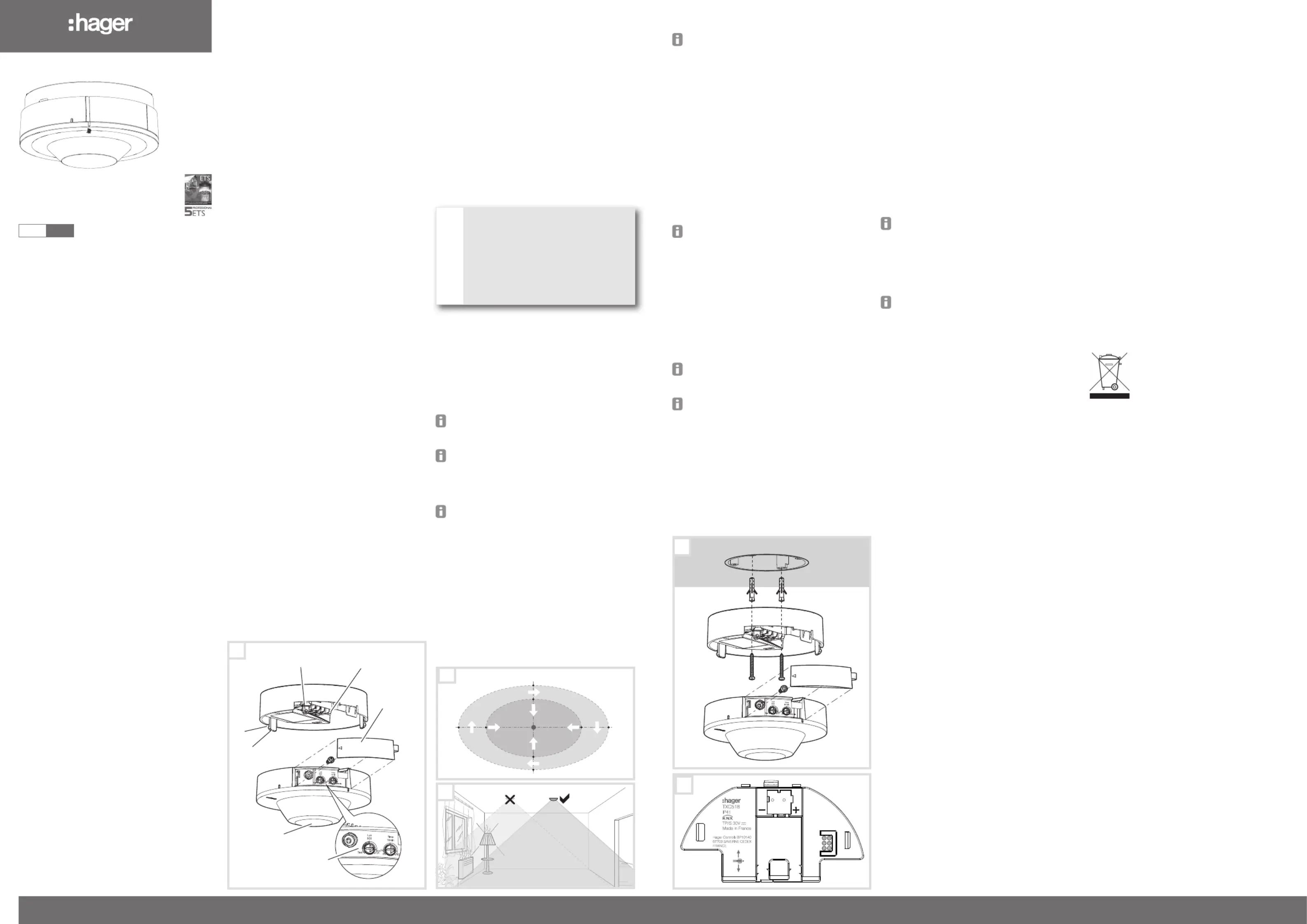
Design and layout of the device
(Figure 1)
(1) Connecting terminals
(2) Security screw fixing point
(3) Unlocking opening
(4) Securing clips
(5) Detector lens with integrated status LED red/
green
(6) Response brightness potentiometer
(7) Delay time potentiometer
(8) Potentiometer cover
(9) Security screw
Function
Correct use
- Automatic transmission of switching commands
for lighting and scene control via the KNX bus
dependent on heat motion and ambient bright-
ness
- Manual control of KNX functions via remote
control (optional, see Accessories)
- Surface-mounted installation or installation on
mounting boxes according to valid standard
(e.g. DIN 4907)
Product characteristics
- Detection of motion especially for areas with
high ceilings
- Response brightness adjustable
- Delay time adjustable
- Master/Slave operation can be parameterised
via ETS
- Optional: Operation modes automatic/semiauto-
matic are adjustable via IR configuration hand-
held controller (see Accessories)
- Test mode
Behaviour during operation
The motion detector detects heat motion caused
by people, animals, or objects in accordance with
IEC 63180.
- Will be switched on for the delay time if move-
ments are detected in the detection area and
the set light level is undershot. Each detected
movement restarts the delay time.
- Will be switched off if no additional movements
are detected in the detection area and the set
delay time has elapsed or the set light level is
exceeded.
Information for electricians
Installation and electrical connection
DANGER!
Electrical shock when live parts are
touched!
An electric shock can lead to death!
Isolate all power before working on
the device and cover any live parts in
the area!
ç
Selecting installation location
The motion detector must be installed horizontally
on the ceiling. It has a detection area of a maxi-
mum of approx. 22 x 12 m. The diameter of the
detection area depends on the installation height.
At an installation height of 8 m, the diameter at
ground level is approx. 22 x 12 m. The diameter of
the inner detection area with enhanced detection
sensitivity is 14 x 8 m (figure 2).
At an installation height greater than 8 m, the
detection area increases. At the same time, the
detection sensitivity decreases.
Observe the motion orientation: A distinction is
made between "direct approach" and "trans-
verse motion". Motions transverse to the motion
detector can be detected better than motions
toward the motion detector (Figure 2).
The device must be completely installed and
closed to meet the degree of protection IP41.
Avoid sources of interference in the detection
area. Sources of interference, e.g. heating
elements, ventilation systems, air conditioners
and lamps that are cooling down can cause
undesired switching (Figure 3).
Select an installation location that is free of
vibration. Vibrations can cause undesired
switching.
Connecting and installing (figure 4)
Observe the installation direction. Install the
device in such a way that the arrow shown in
figure 5 corresponds to the axis of the area to
be monitored.
Feed the connection cable through the cable
entry cut-out (13).
Install device base under the ceiling using
appropriate fixings, a screw & plug set is
included. If available, install device socket in a
flush-mounted box.
Connect the bus cable.
Snap device module onto base.
Screw in security screw (9).
Close cover (8).
Commissioning
The device is in warm-up phase after bus volt-
age recovery (up to 45s). During this time the
status LED is flashing green.
Testing the detection
In test mode, the motion detector works with maxi-
mum response brightness. If movement is detected
the red LED flashes briefly.
Set the potentiometer response brightness (6)
to the Test position (figure1/2).
The device is in test mode.
Carry out test by moving in the detection area.
If the motion detector switches on without mo-
tion in the detection area, then sources of inter-
ference are present (see Installation location).
After 2 minutes in test mode the device is auto-
matically set to the standard values (500 Lux).
Setting the response brightness
The response brightness is the brightness value
saved in the motion detector; when this value is
undershot the connected load is switched on if
movements are detected. The brightness threshold
can be set continuously between approx. 5 and
2000 Lux (daytime operation/brightness-independ-
ent).
Turn the response brightness potentiometer (6)
to the desired position.
Setting the delay time
The delay time is the period of time set in the
motion detector which is the shortest time that the
lighting is switched on when the light level is under-
shot and motion is detected. The delay time can be
set between pulse and approx. 5 s to 60 min.
Turn the delay time potentiometer (7) to the
desired position.
Commissioning with the IR configuration hand-
held controller
The IR configuration hand-held transmitter can
be used to change the values set directly on the
device (see Accessories) if the setting has been
enabled in the ETS.
A detailed description of the EE807 hand-held
controller can be found in the enclosed instruc-
tions.
Operation by IR hand-held controller
The IR hand-held transmitter can be used to trigger
the actions parameterized with the device.
A detailed description of the EE808 hand-held
controller can be found in the corresponding
instructions.
Adjusting the detection area
If the detection area of the detector is too wide or
covers areas that should not be monitored, the
adhesive strips provided can restrict the detection
area if required.
system link: Loading the physical address and
application software
Project planning and commissioning with ETS 5 or
newer.
The device is connected and ready for operation.
Remove cover (8) if there is one.
Set potentiometer delay time (6) .Adr/On
Status LED (5) lights up red.
Load the physical address into the device.
Label the device with the physical address.
Load the application software into the device.
After completion of the loading process or to
cancel, adjust potentiometer delay time.
The status LED (5) goes out.
Snap on cover
easy link:
Information on the system configuration can be
taken from the extensive description of the service
module easy link.
Appendix
Technical data
KNX medium TP 1
Configuration mode S-Mode, E-Controller
Rated voltage KNX 30 V SELV
Current consumption KNX max. 10 mA
Connection mode KNX bus connecting terminal
Response brightness, adjustable 5 ... 2000 Lux
Delay time 5 s ... 60 min
Recommended installation height 6 m ... 9 m
Maximum installation height 10 m
Detection area motion (installation height 8 m)
transversely to detector ~ 22 x 12 m
Towards detector ~ 14 x 8 m
Detection angle approx. 360°
Relative humidity (no condensation) 30°C, 95%
Operating temperature -5 °C ... +45 °C
Storage/transport temperature -20 °C... +70 °C
Degree of protection IP41
Protection class II
Impact resistance IK 04
Operating altitude < 2000 m
Dimensions (Ø x H) 105 x 66.2 mm
Accessories
IR configuration hand-held transmitter EE807
IR hand-held transmitter EE808
Correct Disposal of this product (Waste
Electrical & Electronic Equipment)
(Applicable in the European Union and other
European countries with separate collection
systems).
This marking shown on the product or its literature
indicates that it should not be disposed of with other
household waste at the end of its working life. To prevent
possible harm to the environment or human health from
uncontrolled waste disposal, please separate this device
from other types of waste. Recycle the device responsibly
to promote the sustainable reuse of material resources.
Household users should contact either the retailer where
they purchased this product, or their local government of-
fice, for details of where and how they can take this device
for environmentally safe recycling.
Business users should contact their supplier and check
the terms and conditions of the purchase contract. This
product should not be mixed with other commercial waste
for disposal.
z
3
(1)
(8)
(9)
(2)
(3)
(5)
(4)
(6)
(7)
1
4 m
6 m
7m 11m
11m
7m
4 m
6 m
2
4
5
Bn,.:
M
`
Produkspesifikasjoner
| Merke: | Hager |
| Kategori: | Bevegelsesdetektor |
| Modell: | TXC518 |
Trenger du hjelp?
Hvis du trenger hjelp med Hager TXC518 still et spørsmål nedenfor, og andre brukere vil svare deg
Bevegelsesdetektor Hager Manualer

31 Desember 2025

12 Desember 2024

12 Desember 2024

12 Desember 2024

12 Desember 2024

12 Desember 2024

12 Desember 2024

12 Desember 2024

12 Desember 2024

12 Desember 2024
Bevegelsesdetektor Manualer
- Vimar
- Optex
- EQ-3
- Theben
- Konyks
- Satel
- Megatron
- V-Tac
- D-Link
- Inovonics
- Busch-Jaeger
- ESYLUX
- ABB
- Maxsa
- IFM
Nyeste Bevegelsesdetektor Manualer

8 April 2025

8 April 2025

2 April 2025

2 April 2025

2 April 2025

1 April 2025

28 Mars 2025

28 Mars 2025

5 Mars 2025

5 Mars 2025