IFM PMP094 Bruksanvisning
Les nedenfor 📖 manual på norsk for IFM PMP094 (22 sider) i kategorien sensor. Denne guiden var nyttig for 16 personer og ble vurdert med 4.5 stjerner i gjennomsnitt av 2 brukere
Side 1/22

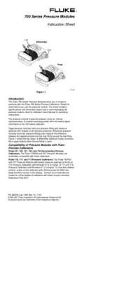
Operating instructions
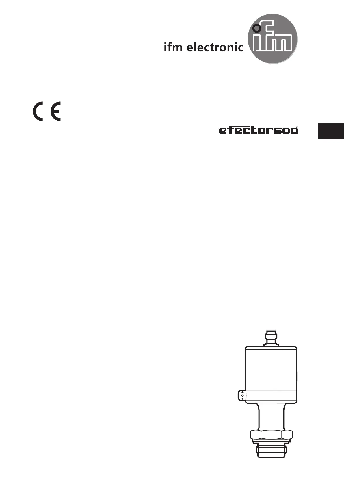
Profibus PA pressure transmitter
PMP0xx
706063/00 06/2011
UK

2
Contents
1 Preliminary note....................................................................................................3
1. Symbols used ...................................................................................................3
2 Safety instructions ................................................................................................3
3 Functions and features .........................................................................................4
4 Function ...............................................................................................................4
5 Installation ............................................................................................................5
6 Electrical connection.............................................................................................7
7 Set-up ...................................................................................................................8
8 Parameter setting .................................................................................................9
8.1 Block model: Pressure transmitter with Profibus PA profile 3.01 ..................10
8.2 Physical Block (PB) ...................................................................................... 11
8.3 Analogue Input Block (AIB) ..........................................................................12
8.4 Pressure Transducer Block (PTB) ................................................................13
8.5 VIEW_1 Parameter (VIEW) ..........................................................................14
8.6 Installation and maintenance parameters (I&M parameters) .......................15
8.7 Typical parameter setting procedures ..........................................................16
8.7.1 Zero point adjustment ..........................................................................16
8.7.2 Damping of the signal measured .........................................................16
8.7.3 Input of the unit of measurement for the pressure ..............................17
8.7.4 Min/max monitoring (lag indicator function) .........................................17
8.7.5 Monitoring the threshold value ............................................................18
8.7.6 Simulation ............................................................................................18
9 Operation ............................................................................................................19
9.1 Communication ............................................................................................19
9.2 Diagnosis and trouble-shooting .................................................................... 21
10 Scale drawing ...................................................................................................23
11 Technical data ................................................................................................... 24

3
UK
1 Preliminary note
1. Symbols used
► Instruction
> Reaction, result
[…] Designation of buttons, switches or indications
→ Cross-reference
Important note
Non-compliance can result in malfunctions or interference.
Information
Supplementary note.
2 Safety instructions
• Please read this document prior to installing the unit. Ensure that the product is
suitable for your application without any restrictions.
• If the operating instructions or the technical data are not adhered to, personal
injury and/or damage to property may occur.
• Checkinallapplicationsthattheproductmaterials(→10Technicaldata)are
compatible with the media to be measured.
• Adheretotheremarksforsafeuseinhazardousareas(→ATEXoperating
instructions).
For units with cULus approval and the scope of validity cULus: The device shall
be supplied from an isolating transformer having a secondary Listed fuse rated as
noted in the following table.
Overcurrent protection
Control-circuit wire size
Maximum protective device rating
Ampere
AWG (mm
2
)
26 (0.13) 1
24 (0.20) 2
22 (0.32) 3
20 (0.52) 5
18 (0.82) 7
16 (1.3) 10
The Sensor shall be connected only by using any R/C (CYJV2) cord, having suitable ratings.
Produkspesifikasjoner
Merke: | IFM |
Kategori: | sensor |
Modell: | PMP094 |
Trenger du hjelp?
Hvis du trenger hjelp med IFM PMP094 still et spørsmål nedenfor, og andre brukere vil svare deg
sensor IFM Manualer

31 Desember 2025

6 Desember 2024

6 Desember 2024

6 Desember 2024

6 Desember 2024

6 Desember 2024

6 Desember 2024

6 Desember 2024

6 Desember 2024

6 Desember 2024
sensor Manualer
- sensor Festo
- sensor Panasonic
- sensor Chauvin Arnoux
- sensor Moen
- sensor Hikvision
- sensor Jung
- sensor Crestron
- sensor Oliveri
- sensor Carrier
- sensor Sensirion
- sensor Metz Connect
Nyeste sensor Manualer

3 April 2025

1 April 2025

1 April 2025

1 April 2025

4 Februar 2025

31 Januar 2025

25 Desember 2024

19 Desember 2024

19 Desember 2024

19 Desember 2024