Kenwood NXR-1700-E Bruksanvisning
Kenwood
Ikke kategorisert
NXR-1700-E
Les nedenfor 📖 manual på norsk for Kenwood NXR-1700-E (24 sider) i kategorien Ikke kategorisert. Denne guiden var nyttig for 9 personer og ble vurdert med 4.4 stjerner i gjennomsnitt av 5 brukere
Side 1/24

B5A-3612-10
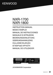
INSTRUCTION MANUAL
MODE D’EMPLOI
MANUAL DE INSTRUCCIONES
MANUALE DI ISTRUZIONI
BEDIENUNGSANLEITUNG
GEBRUIKSAANWIJZING
KULLANIM KILAVUZU
ΕΓΧΕΙΡΊΔΙΟ ΧΡΉΣΤΗ
MANUAL DO UTILIZADOR
NXR-1700
NXR-1800
Produkspesifikasjoner
| Merke: | Kenwood |
| Kategori: | Ikke kategorisert |
| Modell: | NXR-1700-E |
Trenger du hjelp?
Hvis du trenger hjelp med Kenwood NXR-1700-E still et spørsmål nedenfor, og andre brukere vil svare deg
Ikke kategorisert Kenwood Manualer
17 Oktober 2025
6 Oktober 2025
6 Oktober 2025
29 August 2025

23 Februar 2025

23 Februar 2025

23 Februar 2025

9 Desember 2024

9 Desember 2024

16 Oktober 2024
Ikke kategorisert Manualer
- AirTurn
- Gree
- Laserliner
- NGS
- Longvie
- Sonorous
- Sauermann
- JLab
- Nabo
- Generac
- Hayter
- N8WERK
- Yealink
- NUX
- IStarUSA
Nyeste Ikke kategorisert Manualer

23 Oktober 2025

23 Oktober 2025

23 Oktober 2025

23 Oktober 2025

23 Oktober 2025

23 Oktober 2025

23 Oktober 2025

23 Oktober 2025

23 Oktober 2025

23 Oktober 2025