Little Giant VCCA-20-P Bruksanvisning
Little Giant
Vannpumpe
VCCA-20-P
Les nedenfor 📖 manual på norsk for Little Giant VCCA-20-P (24 sider) i kategorien Vannpumpe. Denne guiden var nyttig for 30 personer og ble vurdert med 3.7 stjerner i gjennomsnitt av 15.5 brukere
Side 1/24
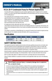
VCCA-20-P Condensate Pump for Plenum Applications
OWNER'S MANUAL
English
EN
The VCCA-20-P pump is designed to be used in plenum applications and is compliant with UL standard
UL2043, “Fire Test for Heat and Visible Smoke Release for Discrete Products and Their Accessories Installed
in Air-handling Spaces.”
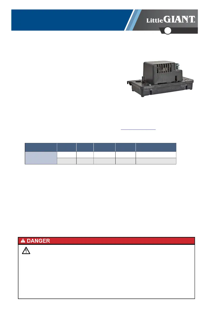
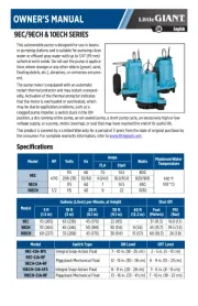
This condensate pump automatically removes condensate
water that drips from an air conditioner evaporator coil, refrig-
eration equipment coil, condensing furnace, or condensing
boiler. The pump is controlled by a float switch mechanism,
which automatically starts and stops the pump.
All models also include a high water level switch, which opens
a thermostat circuit when the pump reservoir is full, stopping production of condensate. Alternatively, this
switch can be reconfigured to close a circuit, which can operate an external alarm or relay, (purchased sep-
arately).
This product is covered by a Limited Warranty for a period of 12 months from the date of original purchase
by the consumer. For complete warranty information, refer to www.LittleGiant.com
.
Specifications
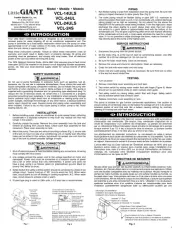
SAFETY INSTRUCTIONS
This equipment should be installed and serviced by technically qualified personnel who are familiar with
the correct selection and use of appropriate tools, equipment, and procedures. Failure to comply with
national and local electrical and plumbing codes and within Little Giant recommendations may result in
electrical shock or fire hazard, unsatisfactory performance, or equipment failure.
Know the product’s application, limitations, and potential hazards. Read and follow instructions carefully to
avoid injury and property damage. Do not disassemble or repair unit unless described in this manual.
Refer to product data plate(s) for additional precautions, operating instructions and specifications.
Failure to follow installation or operation procedures and all applicable codes may result in the following
hazards:
Model Volts HZ Amps Watts Shut Off
VCCA-20-P
115 60 1.5 93 20’ (6.1 m)
230 50/60 0.6/0.5 75 17’ (5.2 m)
Risk of death, personal injury, or property damage due to explosion,
fire, or electric shock.
• Do not use to pump flammable, combustible, or explosive fluids such as gasoline, fuel oil, kerosene, etc.
• Do not use in explosive atmospheres or hazardous locations as classified by the NEC, ANSI/NFPA70.
• Do not handle a pump or pump motor with wet hands or when standing on a wet or damp surface, or in water.
• When a pump is in its application, do not touch the motor, pipes, or water until the unit is unplugged or electri-
cally disconnected.
• If the power disconnect is out of sight, lock it in the open position and tag it to prevent unexpected application of
power.
Produkspesifikasjoner
| Merke: | Little Giant |
| Kategori: | Vannpumpe |
| Modell: | VCCA-20-P |
Trenger du hjelp?
Hvis du trenger hjelp med Little Giant VCCA-20-P still et spørsmål nedenfor, og andre brukere vil svare deg
Vannpumpe Little Giant Manualer
29 August 2025
28 August 2025
27 August 2025
27 August 2025
27 August 2025
27 August 2025
27 August 2025

27 August 2025
27 August 2025

27 August 2025
Vannpumpe Manualer
- Hitachi
- Fieldmann
- Gardenline
- Fujitsu
- Gude
- Stanley
- Dimplex
- Lavor
- Closer Pets
- Silverline
- Hayward
- Anova
- Fluval
- Elpumps
- Eurogarden
Nyeste Vannpumpe Manualer
7 Oktober 2025
7 Oktober 2025
6 Oktober 2025
6 Oktober 2025
6 Oktober 2025
6 Oktober 2025

5 Oktober 2025
5 Oktober 2025
5 Oktober 2025
5 Oktober 2025