Metra AXDIS-PO13 Bruksanvisning
Metra
Ikke kategorisert
AXDIS-PO13
Les nedenfor 📖 manual på norsk for Metra AXDIS-PO13 (6 sider) i kategorien Ikke kategorisert. Denne guiden var nyttig for 4 personer og ble vurdert med 4.3 stjerner i gjennomsnitt av 2.5 brukere
Side 1/6
AXDIS-PO13
INSTALLATION INSTRUCTIONS
AxxessInterfaces.com © COPYRIGHT 2021 METRA ELECTRONICS CORPORATION REV. 10/4/21 INSTAXDIS-PO13
ATTENTION! With the key out of the
ignition, disconnect the negative battery
terminal before installing this product. Ensure
that all installation connections are secure
before cycling the ignition to test this product.
NOTE: Refer to the instructions included with
the aftermarket radio.
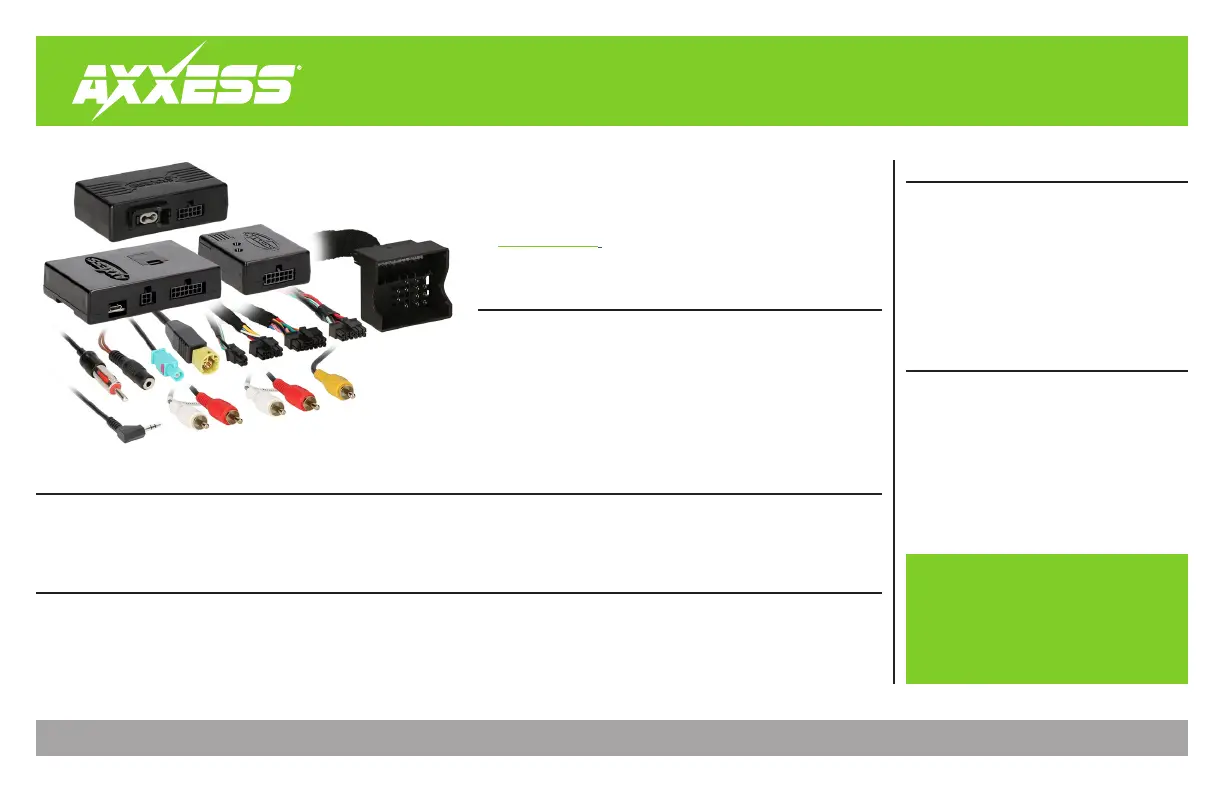
INTERFACE FEATURES
INTERFACE COMPONENTS
TOOLS REQUIRED
• Wire cutter
• Crimp tool and connectors
(ex. butt splice connectors, bellcaps, etc.)
or
• Solder gun, solder, and heat shrink
• Tape
• Zip-ties
TABLE OF CONTENTS
Connections ............................................................2
Installing the AXDIS-PO13 interface ......................3
Installing the Fiber Optic Cable.............................3
Programming the AXSWC interface .....................4
Data Interface with SWC
Porsche (with MOST 25 amp) 2010-2016
APPLICATIONS
• Provides accessory power
• Retains RAP
(retained accessory power)
• Designed for MOST fiber
amplified system
• Retains reverse camera
• Micro-B USB updatable
• Provides NAV outputs (parking
brake, reverse, speed sense)
• Retains steering wheel controls
• Retains balance
Porsche
Panamera 2010-2016 PCM 3.1
Cayenne 2012-2016 PCM 3.1
911 (991) 2012-2016 PCM 3.1
2008-up
Pontiac
Xxxxxxx 2007-2008
Xxxxxxx 2009
• AXDIS-PO13 interface • AXDIS-PO13 harness • AXDIS-PO13 MOST-25 amplifier interface • AXSWC harness • AXSWC interface
• Female 3.5mm connector with stripped leads
Visit axxessinterfaces.com for more detailed information about the product and up-to-date
vehicle specific applications
Produkspesifikasjoner
| Merke: | Metra |
| Kategori: | Ikke kategorisert |
| Modell: | AXDIS-PO13 |
Trenger du hjelp?
Hvis du trenger hjelp med Metra AXDIS-PO13 still et spørsmål nedenfor, og andre brukere vil svare deg
Ikke kategorisert Metra Manualer

11 Oktober 2025
10 Oktober 2025

10 Oktober 2025
10 Oktober 2025
10 Oktober 2025
10 Oktober 2025
10 Oktober 2025
10 Oktober 2025
10 Oktober 2025
9 Oktober 2025
Ikke kategorisert Manualer
- Nabo
- Insignia
- Drayton
- PCE
- Black Hydra
- Bowflex
- SuperTooth
- Stairville
- Yphix
- Seagate
- Varytec
- Kaiser Nienhaus
- Osprey
- ChyTV
- Quantum
Nyeste Ikke kategorisert Manualer

23 Oktober 2025

23 Oktober 2025

23 Oktober 2025

23 Oktober 2025

23 Oktober 2025

23 Oktober 2025

23 Oktober 2025

23 Oktober 2025

23 Oktober 2025

23 Oktober 2025