Omega Excalibur RS-475-3D Bruksanvisning
Omega
Fjernkontroll
Excalibur RS-475-3D
Les nedenfor 📖 manual på norsk for Omega Excalibur RS-475-3D (42 sider) i kategorien Fjernkontroll. Denne guiden var nyttig for 7 personer og ble vurdert med 3.6 stjerner i gjennomsnitt av 4 brukere
Side 1/42

INSTALLATION GUIDE
RS-X70
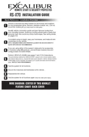
Choose a discreet mounting location for the module and locations
for any accessories (siren, sensors, interface module, etc.). Do not
mount the module yet (you might anger the install gods).
Identify vehicle connection points and plan harness routing from
your mounting location. Avoid any moving vehicle parts or parts that
generate heat. Also avoid any sharp metal edges. See wiring details
on pages 3-9.
Cut system wires to length, prep your harnesses, and make all wire
connections to the vehicle.
NOTE: DATA/MUX WIRES ARE SENSITIVE and MUST BE SPLICED DIRECTLY.
QUICK TAPS ARE NOT RECOMMENDED.
If you are using either of the system’s data ports for accessories
or modules using DBI protocol, connect these modules now and
congure them for DATA MODE.
Perform VEHICLE LEARN (see pages 7 and 10 for instructions).
This automatically matches the IGN/ACC/START outputs to the vehicle’s ignition switch,
auto-detects data protocols, chooses the best engine detection method, decides whether
neutral safety circuit is required, and allows you to quickly set engine and transmission
types. FASTER THAN PROGRAMMING!
Test the system for all functions.
Secure the module(s) and harnesses to the vehicle.
Reassemble the vehicle.
Test the system for all functions again (keep the install gods happy).
Quick Reference - Installation Overview
1
2
3
4
5
6
7
8
9
WIRE DIAGRAM: CENTER OF THIS BOOKLET
FEATURE CHART: BACK COVER
REMOTE START & SECURITY PERFECTED

Table Of Contents
Installation Considerations .................................................................... 3
6 Pin Main Wire Harness ......................................................................... 3
Red & Red/White Wires - Constant Power (+) Input ............................. 3
Pink Wire - IGNITION/ACC/START (+) Input/Output ............................. 3
Orange Wire - ACCESSORY/IGN/START (+) IN/Out ............................ 4
Violet Wire - Start (+) INPUT/Output ..................................................... 4
Pink/White Wire - IGNITION/ACC/START (+) In/Out ............................ 4
14 Pin Secondary Wire Harness ............................................................. 4
Black Wire - System Ground (-) Input ................................................... 4
Orange Wire - Status/Anti-grind (-) Output ............................................ 4
Brown/Red Wire - Brake Pedal (+) Input ............................................... 4
Black/White Wire - Neutral Safety (-) Input ........................................... 5
Violet/White Wire - Tach Signal Input .................................................... 5
Brown Wire - Horn (-) Output ................................................................ 5
White Wire - Flashing Light (+) Output .................................................. 5
White/Black Wire - Flashing Light (-) Output ......................................... 5
Gray Wire - Hood Trigger (-) Input ......................................................... 5
14 Pin Secondary Wire Harness (cont’d) .............................................. 8
Yellow - Alarm Ignition Control (+) Output ............................................. 8
White/Blue Wire - Remote Start Activation (-) Input .............................. 8
Lt. Green/Red Wire - OEM Alarm Arm (-) Output .................................. 8
Lt. Green/Black Wire - OEM Alarm Disarm (-) Output ........................... 8
Red/White Wire - Trunk Release / CH2 (-) Output ................................ 8
Green & Black Data Ports ....................................................................... 8
3 Pin Satellite Relay Port (RED) ............................................................. 9
3 Pin Door Lock/Unlock Port (RED) ....................................................... 9
Status Lights ............................................................................................ 9
Valet / Programming Button ................................................................... 9
Window Mount Antenna Module .......................................................... 10
Tach Programming ................................................................................ 11
Programming Transmitters................................................................... 11
Programming Features ......................................................................... 11
This device complies with FCC Rules part 15. Operation is subject to the fol-
lowing two conditions, (1) This device may not cause harmful interference and,
(2) This device must accept any interference that may be received, including
interference that may cause undesired operation.
The manufacturer is not responsible for any radio or TV interference caused
by unauthorized modications to this equipment. Such modications could void
the user’s authority to operate the equipment.
2
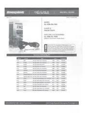
Produkspesifikasjoner
Merke: | Omega |
Kategori: | Fjernkontroll |
Modell: | Excalibur RS-475-3D |
Trenger du hjelp?
Hvis du trenger hjelp med Omega Excalibur RS-475-3D still et spørsmål nedenfor, og andre brukere vil svare deg
Fjernkontroll Omega Manualer
29 August 2025
28 August 2025
27 August 2025
27 August 2025
27 August 2025
27 August 2025
27 August 2025
Fjernkontroll Manualer
- Velleman
- Vizio
- Multibrackets
- Lutron
- URC
- Compustar
- Aplic
- American DJ
- Furman
- Infinity
- Reely
- Phoenix Technologies
- Hannspree
- Nexa
- Irradio
Nyeste Fjernkontroll Manualer
10 Oktober 2025
9 Oktober 2025
5 Oktober 2025
5 Oktober 2025
4 Oktober 2025
3 Oktober 2025
3 Oktober 2025
2 Oktober 2025
2 Oktober 2025
2 Oktober 2025