Ozito IAW-120 Bruksanvisning
Les nedenfor 📖 manual på norsk for Ozito IAW-120 (20 sider) i kategorien sveis. Denne guiden var nyttig for 15 personer og ble vurdert med 5.0 stjerner i gjennomsnitt av 8 brukere
Side 1/20
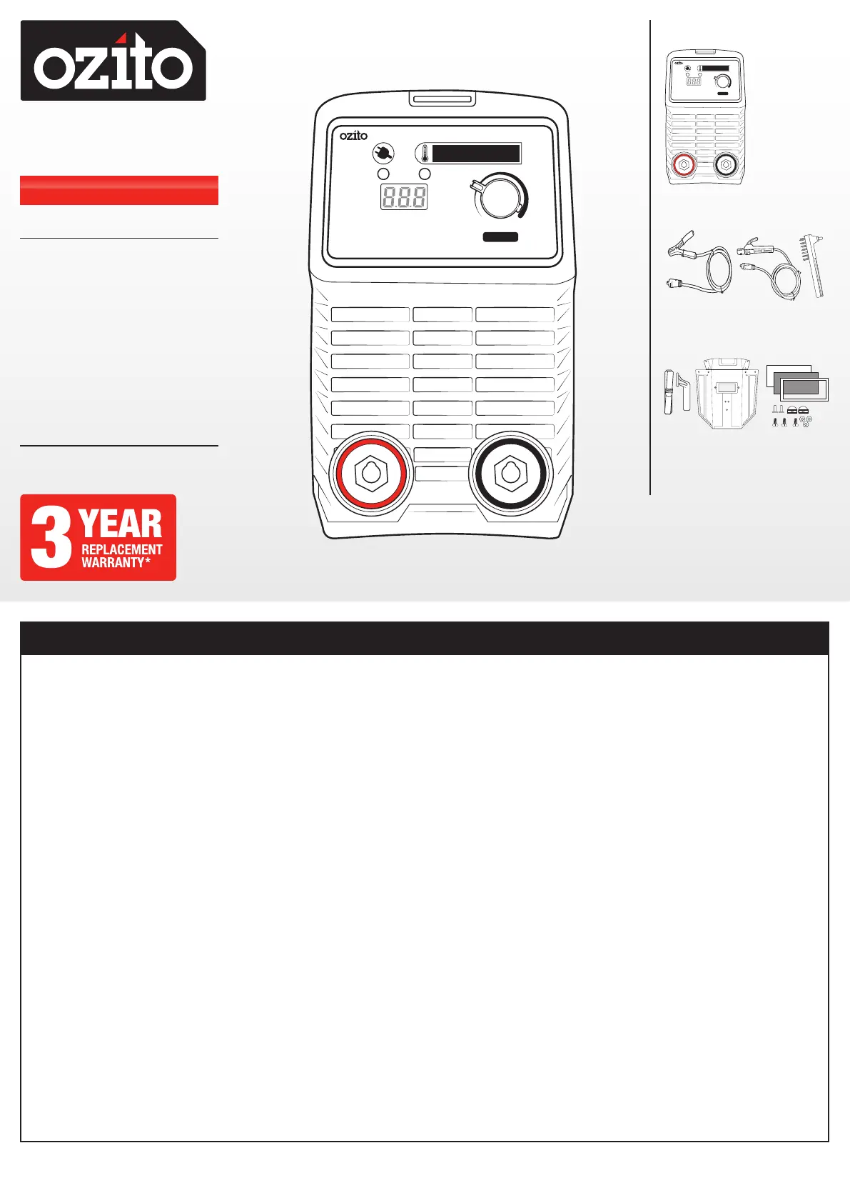
MIN MAX
ON
THERMAL OVERLOAD PROTECTION
ALLOW WELDER TO COOL DOWN
A
CURRENT
120A
INVERTER
ARC WELDER
MIN MAX
ON
THERMAL OVERLOAD PROTECTION
ALLOW WELDER TO COOL DOWN
A
CURRENT
120A
INVERTER
ARC WELDER
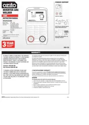
INVERTER ARC
WELDER
120A
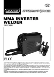
INSTRUCTION MANUAL
SPECIFICATIONS
Mains Voltage: 240V ~ 50Hz
Welding Current: 20-120A (20.8 - 24.8V)
Duty Cycle: 15% @120A (24.8V DC)
60% @60A (22.4V DC)
100% @50A (22.0V DC)
The duty cycle was determined at 40°C
by simulation.
Arc Electrode Size: 1.6-3.2mm
IP Rating: IP21S
Weight: 3.0kg
* Additional specifications provided under equipment
classification.
IAW-120
STANDARD EQUIPMENT
3 YEAR REPLACEMENT WARRANTY*
Your product is guaranteed for a period of 36 months from the original date of purchase. If
a product is defective it will be replaced in accordance with the terms of this warranty. Warranty
excludes consumable parts, for example: valve adapters and accessories.
*This product is intended for DIY use only and replacement warranty covers domestic use.
WARNING
The following actions will result in the warranty being void.
• If the tool has been operated on a supply voltage other than that specified on the tool.
• If the tool shows signs of damage or defects caused by or resulting from abuse, accidents
or alterations.
• Failure to perform maintenance as set out within the instruction manual.
• If the tool is disassembled or tampered with in any way.
• Professional, industrial or high frequency use.
WARRANTY
OZITO Australia/New Zealand (Head Office) 25 Fox Drive, Dandenong South, Victoria, Australia 3175.
ozito.com.au
Inverter Arc Welder
Earth Clamp, Arc Electrode Holder &
Chipping Hammer/Wire Brush
Strap, Handle, Welding Mask, Lens
Assembly & Fasteners
0321
IN ORDER TO MAKE A CLAIM UNDER THIS WARRANTY
YOU MUST RETURN THE PRODUCT TO YOUR NEAREST
BUNNINGS WAREHOUSE WITH YOUR BUNNINGS
REGISTER RECEIPT. PRIOR TO RETURNING YOUR
PRODUCT FOR WARRANTY PLEASE TELEPHONE OUR
CUSTOMER SERVICE HELPLINE:
Australia: 1800 069 486
New Zealand: 0508 069 486
The benefits provided under this warranty are in addition to other rights and remedies which
are available to you at law.
Our goods come with guarantees that cannot be excluded at law. You are entitled to a
replacement or refund for a major failure and for compensation for any other reasonably
foreseeable loss or damage. You are also entitled to have the goods repaired or replaced if the
goods fail to be of acceptable quality and the failure does not amount to a major failure.
Generally you will be responsible for all costs associated with a claim under this warranty,
however, where you have suffered any additional direct loss as a result of a defective product
you may be able to claim such expenses by contacting our customer service helpline above.
TO ENSURE A SPEEDY RESPONSE PLEASE HAVE
THE MODEL NUMBER AND DATE OF PURCHASE
AVAILABLE. A CUSTOMER SERVICE REPRESENTATIVE
WILL TAKE YOUR CALL AND ANSWER ANY QUESTIONS
YOU MAY HAVE RELATING TO THE WARRANTY POLICY
OR PROCEDURE.
Produkspesifikasjoner
| Merke: | Ozito |
| Kategori: | sveis |
| Modell: | IAW-120 |
Trenger du hjelp?
Hvis du trenger hjelp med Ozito IAW-120 still et spørsmål nedenfor, og andre brukere vil svare deg
sveis Ozito Manualer
3 August 2025
3 August 2025
sveis Manualer
Nyeste sveis Manualer

23 Oktober 2025
21 Oktober 2025
21 Oktober 2025
21 Oktober 2025
20 Oktober 2025
6 Oktober 2025
6 Oktober 2025
6 Oktober 2025
5 Oktober 2025

4 Oktober 2025