Qubino Flush PWM Bruksanvisning
Les nedenfor 📖 manual på norsk for Qubino Flush PWM (2 sider) i kategorien Termostat. Denne guiden var nyttig for 36 personer og ble vurdert med 4.9 stjerner i gjennomsnitt av 18.5 brukere
Side 1/2
Qubino
The INNOVATIVE SMALLESTand
Flush PWM Thermostat
ORDERING CODE
Z-WAVE FREQUENCY
ZMNHLD1
868,4 MHz
ZMNHLD2
921,4 MHz
ZMNHLD3
908,4 MHz
ZMNHLD4
869,0 MHz
ZMNHLD5
916,0 MHz
ZMNHLD8
865,2 MHz
This Z-Wave module is used to regulate temperature.
Regulation is done using full wave PWM technology. The
module can be controlled either through Z-wave network or
through the wall switch.
The module is designed to be mounted inside a flush “
mounting and is hidden behind a traditional wall switch. box”
Module measures power consumption of connected device.
It is designed to act as repeater in order to improve range
and stability of Z-wave network.
Supported switches
Module supports switches (push button) and mono-stable
bi-stable switches. The module is factory set to operate
with -stable switches. bi
Installation
To prevent electrical shock and/or equipment damage,
disconnect electrical power at the main fuse or circuit
breaker before installation or any servicing.
Make sure, that no voltage is present in the installation.
Prevent the disconnecting device from being switched
on accidentally.
Connect the module according to electrical diagram.
Locate the antenna far from metal elements (as far as
possible).
Do not shorten the antenna.
Danger of electrocution!
Module installation requires a great degree of skill and
may be performed only by a qualified and licensed
electrician.
Even when the module is turned off, voltage may be
present on its terminals. Any works on configuration
changes related to connection mode or load must be
always performed by disconnected power supply (disable
the fuse).
Note!
Do not connect the module to loads exceeding
recommended values. Connect the module only in
accordance to the below diagrams. Improper connections
may be dangerous.
Electrical installation must be protected by directly
associated over current protection fuse 1A, gG or Time
lag T, rated breaking capacity 1500A (ESKA 522.717)
must be used according to wiring diagram to achieve
appropriate overload protection of the module. The
fuse must be installed in fuse holder type: Adels
contact 503 Si / 1 DS
Package contents:
Flush PWM thermostat + Temperature sensor
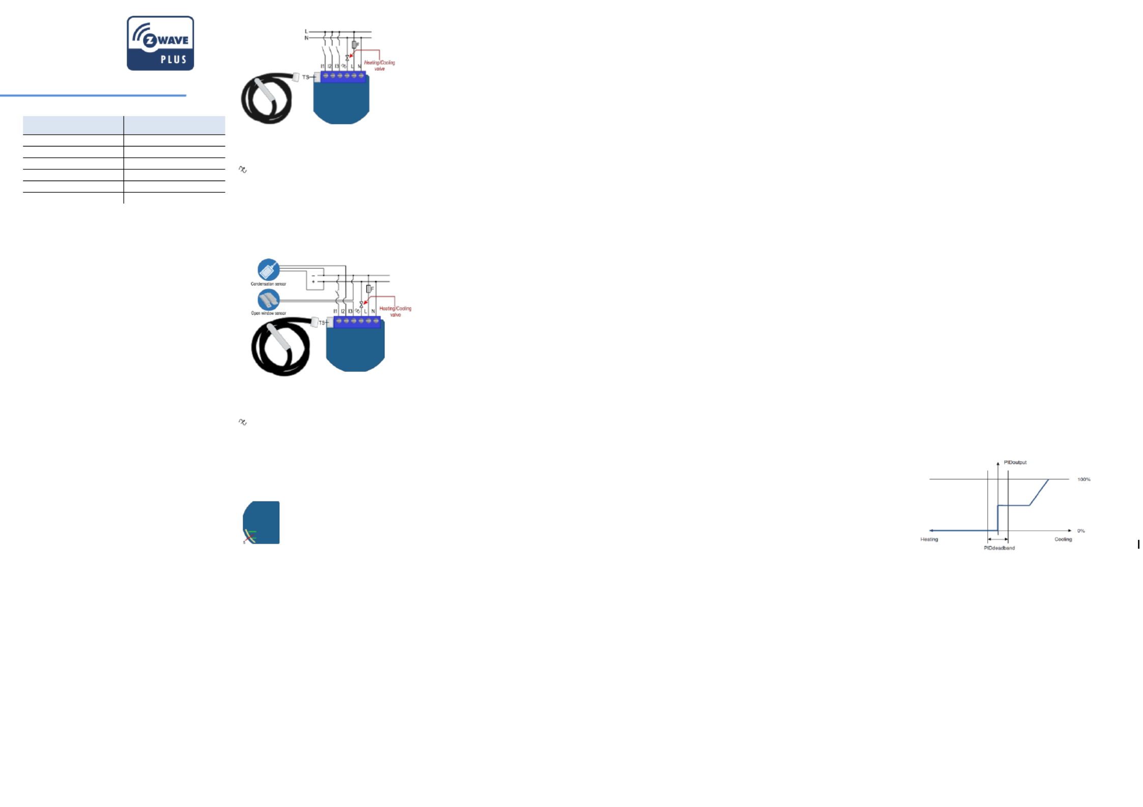
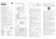
Electrical diagram 230VAC
Notes for the diagram:
N
Neutral lead
L
Live lead
Output
I3
Input for switch /push button or sensor*
I2
Input for switch /push button or sensor*
I1
Input for switch /push button or sensor*
TS
Terminal for digital temperature sensor (only for
Flush PWM thermostat module compatible digital
temperature sensor).
*For details please check parameters 11, 12 and 1 3
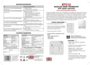
Electrical diagram 24VDC
Notes for the diagram:
N
+ VDC
L
- VDC
Output
I3
Input for switch /push button or sensor*
I2
Input for switch /push button or sensor*
I1
Input for switch /push button or sensor*
TS
Terminal for digital temperature sensor (only for
Flush PWM thermostat module compatible digital
temperature sensor).
*For details please check parameters 11, 12 and 1 3
WARNING: Service button S when must NOT be used
module is connected to 110-230V power supply.
WARNING: the temperature sensors should not be
exposed to water.
Module Inclusion (Adding to Z-wave network)
Connect module to power supply (with
temperature sensor connected ),
enable add/remove mode on main controller
auto-inclusion (works for about 5 seconds after
connected to power supply) or
press push button I1 three times within 3s (3 times
change switch state within 3 seconds) or
press service button (only applicable for 24 V SELV S
supply voltage) for more than 2 second.
NOTE 1: For auto-inclusion procedure, first set main
controller into inclusion mode and then connect module to
power supply.
NOTE 2: When connecting temperature sensor to module
that has already been included, you have to exclude
module first. Switch off power supply, connect the sensor
and re-include the module.
Module Exclusion/Reset (Removing from
wireless network)
Connect module to power supply
bring module within maximum 1 meter (3 feet) of the
main controller,
enable add/remove mode on main controller
press push button I1 five times within 3s (5 times change
switch state within 3 seconds) in the first 60 seconds after
the module is connected to the power supply or
press service button (only applicable for 24 V SELV S
supply voltage) for more than 6 second.
By this function all parameters of the module are set to
default values and own ID is deleted.
If push button I1 is pressed three times within 3s (or service
button S is pressed more than 2 and less than 6 seconds)
module is excluded, but configuration parameters are not
set to default values.
NOTE: If the module is included with parameters 100,101
or 102 with values different to default and module reset is
done, wait at least 30s before next inclusion.
Association
Association enables thermostat module to transfer PWM
commands inside Z-Wave network directly (without main
controller) to other Z-Wave modules.
Associated Groups:
Group 1: Lifeline group (reserved for communication with
the main controller), 1 node allowed.
Group 2: basic on/off (triggered at change of the output Q
state and reflecting its state) up to 16 nodes.
Group 3: SENSOR_MULTILEVEL_GET (triggered once per
minute if Parameter 121 is not 0) up to 16 nodes.
Group 4: basic on/off (triggered by Too high temperature
limit, it send 0x00 in Heating mode and in Cooling 0xFF
mode, trigged by Too low temperature limit, it send 0x00 in
Heating mode and 0xFF in Cooling mode; hysteresis is 1°C)
up to 16 nodes.
Group 5: THERMOSTAT_SETPOINT_G (triggered once ET
per minute if Parameter 121 is not 0) up to 16 nodes.
Group 6: basic on/off (trigged by change of I1 if window
sensor functionality is selected by parameter no. 11) up to
16 nodes.
Group 7: basic on/off (trigged by change of I2 if condense
sensor functionality is selected by parameter no. 12) up to
16 nodes.
Group 8: basic on/off (trigged by change of I3 if flood
sensor functionality is selected by parameter no. 13) up to
16 nodes.
Group 9: sensor multilevel report (trigged by change of
temperature) up to 16 nodes.
Group 10: Basic on/off (triggered by change of the output Q
state and reflecting its state), up to 16 nodes,
Basic Set ON command is delayed for the time defined in
parameter no. 77.
Basic Set OFF command is reported immediately.
Configuration parameters
Parameter no. 1 Input I1 switch type –
Available config. parameters (data type is 1 Byte DEC):
default value 1
- mono-stable switch type (push button) 0
- -stable switch type 1 bi
Parameter no. 2 Input I2 switch type –
See parameter 1 (valid for I2 instead of I1)
Parameter no. 3 Input I3 switch type –
See parameter 1 (valid for I3 instead of I1)
Parameter no. 4 Input 1 contact type –
Available config. parameters (data type is 1 Byte DEC):
default value 0
- NO (normally open) input type 0
- NC (normally close) input type 1
NOTE: This parameter has influence only when parameter
no. 11 is set to the value “2”. After setting this parameter,
switch the window sensor once, so that the module could
determine the input state.
Parameter no. 5 Input 2 contact type –
See parameter 4 (valid for I2 instead of I1)
NOTE: This parameter has influence only when parameter
no. 12 is set to the value “2000”. After setting this
parameter, switch the condense sensor once, so that the
module could determine the input state.
Parameter no. 6 Input 3 contact type –
See parameter 4 (valid for I3 instead of I1)
NOTE: This parameter has influence only when parameter
no. 13 is set to the value “2”. After setting this parameter,
switch the flood sensor once, so that the module could
determine the input state.
Parameter no. 10 - Activate / deactivate functions ALL
ON/ALL OFF
Available config. parameters (data type is 2 Byte DEC):
default value 255
- ALL ON active, ALL OFF active. 255
- ALL ON is not active ALL OFF is not active 0
- ALL ON is not active ALL OFF active 1
- ALL ON active ALL OFF is not active 2
Flush thermostat module responds to commands ALL PWM
ON / ALL OFF that may be sent by the main controller or by
other controller belonging to the system.
Parameter no. 11- I1 Functionality selection
Available config. parameters (data type is 2 Byte DEC):
default value 1
input I1 doesn Heat/Cool 32767 – ’t influence on the
process
- input I1 changes the mode of the thermostat 1
between Off and Heat/Cool. In this case function on window
sensor is disabled
- input I1 influences on heating/cooling valves 2
according to status of window sensor. In this case function
of Off and Heat/Cool selection by I1 is disabled.
NOTE: If "Window Sensor" selected (value set to "2"),
parameter 100 (enable/disable endpoint) must be set to
non zero value and module re-included!
Parameter no. 12 I2 Functionality selection –
Available config. parameters (data type is 2 Byte DEC):
default value 32767
- input I2 does not influence on the Heat/Cool 32767
process
From 0 to 990 - Temperature set point from 0.0 °C to
99.0 °C. When I2 is pressed, it automatically set
temperature setpoint according to value defined here. In
this case function of condense sensor is disabled
From 1001 to 1150 - Temperature set point from -0.1
°C to 15.0 °C- . When I2 is pressed, it automatically set
temperature setpoint according to value defined here. In
this case function of condense sensor is disabled
- Input I2 influences on the cooling valve 2000
according to status of condense sensor, In this case
function of setpoint selection with I2 is disabled
NOTE: If "Condense Sensor" selected (value set to "2000"),
parameter 101 (enable/disable endpoint) must be set to
non zero value and module re-included!
Parameter no. 13 I3 Functionality selection –
Available config. parameters (data type is 2 Byte DEC):
default value 32767
- input I3 does not influence on the heat/cool 32767
process
- input I3 changes the mode of the thermostat 1
between Heat and Cool and override parameter 59. In this
case function on flood sensor is disabled NOTE: After
parameter change, first exclude module (without setting
parameters to default value) and then re include the
module!
- input I3 influences on heating/cooling valves 2
according to status of flood sensor. In this case function of
Heat/Cool selection by I3 is disabled
NOTE1 If this parameter is changed, it is necessary to re-:
include the module.
NOTE2: If "Flood Sensor" selected (value set to "2"),
parameter 102 (enable/disable endpoint) must be set to
non zero value and module re-included!
Parameter no. 40 Power reporting in Watts on power –
change
Set value means percentage, set value from 0 - 100=0% -
100%. Available configuration parameters (data type is 1
Byte DEC):
default value 0
- reporting disabled 0
1-100 = 1%-100% Reporting enabled. Power report is
send (push) only when actual power in Watts in real time
changes for more than set percentage comparing to
previous actual power in Watts, step is 1%.
NOTE If power changed is less than 1W, the report is not :
send (pushed), independent of percentage set.
Parameter no. 42 Power reporting in Watts by time –
interval
Set value means time interval (0 ) in seconds, –32767
when power report is send. Available config. parameters
(data type is 2 Byte DEC):
default value 0 (power report is disabled)
- reporting disabled 0
- 1 32767 32767 = 1 second - seconds. Reporting
enabled. Power report is send with time interval set by
entered value.
Parameter no. 45 –Antifreeze
Set value means at which temperature the device will be
turned on even if the thermostat was manually set to off.
Available config. parameters (data type is 2 Byte DEC):
default value 50 (5,0 °C)
- 0 127 = 0,0°C … 12,7 °C
- 1127 = - - 1001 0,1°C … 12,6 °C
- Antifreeze functionality disabled 255
NOTE: Antifreeze is activated only in heating mode.
Parameter no. 50 - PWM maximum value
Available config. parameters (data type is 1 Byte DEC):
default value 100 (Maximum PWM value)
2-100 = 2%-100%, step is 1%. Maximum PWM set by
entered value
NOTE: The maximum level may not be lower than the
minimum level!
Parameter no. 51 - PWM minimum value
Available config. parameters (data type is 1 Byte DEC):
Default value 0 (Minimum dimming value is 0%)
1- 99 = 1% - 99%, step is 1%. Minimum PWM set by
entered value.
NOTE: The minimum level may not exceed max. level!
Parameter no. 52 - PWM cycle duration
Available config. parameters (data type is 1 Byte DEC):
default value 10 (Minimum dimming value is 0%)
- 127 = 1 - 127s, step is 1s. PWM cycle duration set 5
by entered value.
NOTE: PWM cycle duration define the summary of all ON
plus OFF time periods. For example if Output is set to 70%
with PWM cycle duration of 20s, output will be ON for 14s
then OFF 6s, again 14s ON, etc…
Parameter no. 53 - PID value inside deadband
Available config. parameters (data type is 1 Byte DEC):
default value 0 (PID value equal PWM minimum
value)
- PID value set to LAST VALUE 1
NOTE: When value is set to PID inside deadband is “0” ,
forced to PWM minimum value. LASTVALUE means that
PID remains on same level as was before entering into
deadband.
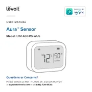
Parameter no. 54 - PID deadband
Available config. parameters (data type is 1 Byte DEC):
default value 5 (0,5 °C)
0- - 127 0.0 °C to 12.7 °C, step is 0,1°C
NOTE: This parameter defines the zone where PID is not
active. If the temperature difference between actual and
setpoint is bigger than PID deadband, then the PID will start
to regulate the system, otherwise the PID is zero or fixed.
Parameter no. 55 - Integral sampling time
Available config. parameters (data type is 1 Byte DEC):
default value 5 (5s)
0- - 0s to 127s, step is 1s 127
Parameter defines the time between samples. On each
sample the controller capture difference between SP-act.
Parameter no. 56 - P parameter
Available config. parameters (data type is 2 Byte DEC):
default value 100
-1000 - P value, step is 1 0
Parameter no. 57 - I parameter
Available config. parameters (data type is 2 Byte DEC):
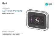
S
Service button (used to add or
remove module from the Z-
Wave network in case of 24 V
SELV power supply).
Produkspesifikasjoner
| Merke: | Qubino |
| Kategori: | Termostat |
| Modell: | Flush PWM |
Trenger du hjelp?
Hvis du trenger hjelp med Qubino Flush PWM still et spørsmål nedenfor, og andre brukere vil svare deg
Termostat Qubino Manualer

27 Oktober 2024

18 Oktober 2024
Termostat Manualer
- Vaillant
- Nest
- Renkforce
- Itho-Daalderop
- ATAG
- Stiebel Eltron
- Tellur
- OJ ELECTRONICS
- MundoControl
- Worcester-Bosch
- Devi
- Innogy
- Brink
- Braeburn
- GE
Nyeste Termostat Manualer

19 Oktober 2025
19 Oktober 2025
9 Oktober 2025
8 Oktober 2025
6 Oktober 2025
6 Oktober 2025
6 Oktober 2025
24 September 2025
24 September 2025
24 September 2025