RDL HD-RA35UA Bruksanvisning
Les nedenfor 📖 manual på norsk for RDL HD-RA35UA (3 sider) i kategorien miksestav. Denne guiden var nyttig for 20 personer og ble vurdert med 4.5 stjerner i gjennomsnitt av 10.5 brukere
Side 1/3
INSTALLATION AND OPERATION
INTRODUCTION
INPUT WIRING
PRIORITY PAGING
INPUTS 3 & 4
INPUT 1 INPUT 2
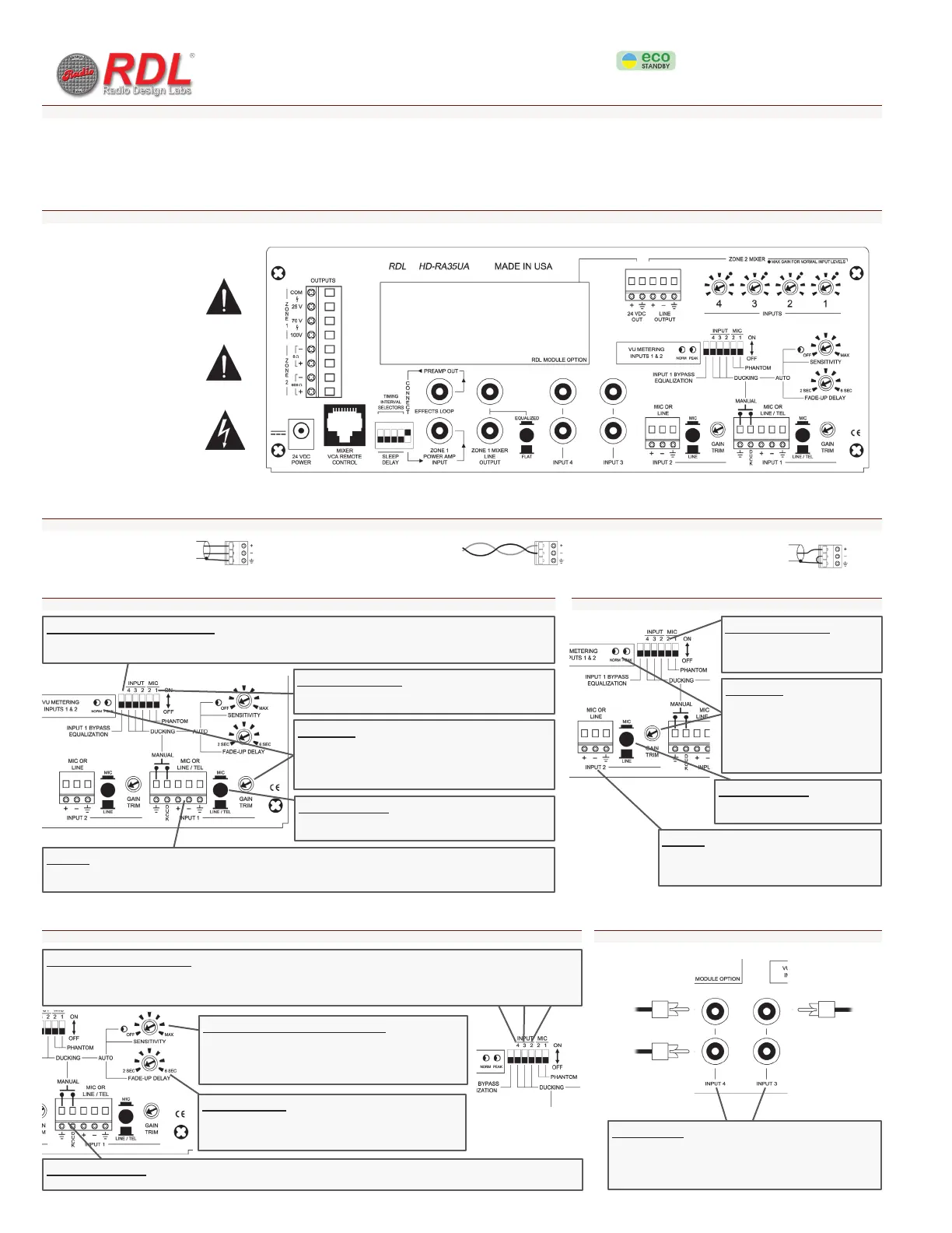
CONNECTIONS
Four inputs may be connected. Each input is available on the primary Zone 1 front-panel mixer and on the Zone 2 rear-panel mixer. If used, the paging source is usually connected to Input 1.
The front-end preamplifier stages for Inputs 1 and 2 are each equipped with a gain trimmer. The dual-LED VU meter displays the signal level for Inputs 1 and 2 following the preamplifiers. This
allows each input gain trimmer to be set properly for the optimum signal-to-noise ratio, avoiding the possibility of input clipping common to mixers with unmetered input stages.
Connections are made on the rear panel. All connections are on detachable terminal blocks or connectors. The Zone 2 mixer, Inputs 1 and 2 gain trimmers and VU-meter, ducking controls and
assignments, phantom voltage selectors and sleep mode delay timer settings are also provided on the rear panel. The Zone 1 mixer, tone controls, indicators and power button are on the front panel.
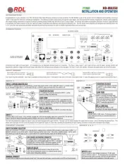
Balanced MIC or LINE source connected
using a single-pair shielded audio cable
Unbalanced MIC or LINE source connected using
a single-conductor shielded audio cable
Balanced LINE signal from phone
PBX or audio transformer
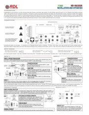
INPUT 1
Connect a MIC or LINE source. This is normally a paging mic or the line-level paging output from a phone PBX. The line-level
input is transformer balanced (providing galvanic isolation) and may be connected balanced or unbalanced.
INPUT 2
Connect a MIC or LINE source. The line-level input is
active balanced and may be connected balanced or
unbalanced.
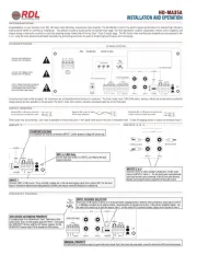
INPUTS 3 & 4
Connect a mono or stereo standard unbalanced -10 dBV audio
source to INPUTs 3 and/or 4. The two input jacks associated with
each input provide active summing of the left and right channels,
thereby preserving the stereo separation of the audio source.
MIC or LINE Gain
Set the Input Gain to MIC or LINE/TEL according to the input
signal connected.
MIC or LINE Gain
Set the Input Gain to MIC or LINE
according to the input signal connected.
GAIN TRIM
Feed a normal signal level into INPUT 1 and adjust the GAIN
TRIM for maximum brightness of the NORM green LED with
occasional flashing of the red PEAK LED. (Disconnect INPUT 2
during this adjustment.)
GAIN TRIM
Feed a normal signal level into
INPUT 2 and adjust the GAIN TRIM
for maximum brightness of the NORM
green LED with occasional flashing
of the red PEAK LED. (Disconnect
INPUT 1 during this adjustment.)
VOX (VOICE-ACTIVATED PRIORITY)
If a paging signal is to automatically “duck” (fade down) other
audio inputs, feed a normal paging signal into INPUT 1 and adjust
the SENSITIVITY trimmer until the LED flashes regularly. Set the
SENSITIVITY trimmer fully CCW to disable the VOX function.
MANUAL PRIORITY
If a swich (such as a paging mic push-to-talk switch) should “duck” (fade down) other audio inputs, connect the switch to the DUCK and Ground terminals.
INPUT DUCKING SELECTOR
Select any or all inputs (2, 3 and/or 4) to be ducked when a paging priority is detected (VOX activated by audio signal on INPUT 1, or
MANUAL activation by an external switch. Selected inputs are ducked only in Zone 1 (the primary amplified output). Set the switch
ON (switch up) to duck the input in Zone 1; set the switch OFF to prevent ducking. Inputs are not ducked in Zone 2.
FADE-UP DELAY
Adjust the FADE-UP DELAY trimmer to delay the start of the
audio fade-up following the release of an external manual priority
switch and/or VOX priority detection.
PHANTOM VOLTAGE
If a condenser mic may be connected to INPUT 1, set the
phantom voltage ON (switch up).
INPUT 1 BYPASS EQUALIZATION
If the INPUT 1 (paging) signal equalization is to be adjusted by the front-panel tone controls, set the switch OFF (down). If the
tone controls are
not
intended to adjust the frequency response of INPUT 1, set the switch ON (up).
PHANTOM VOLTAGE
If a condenser mic may be connected
to INPUT 2, set the phantom voltage
ON (switch up).
LEFT
STEREO SOURCE MONO SOURCE
RIGHT
HD-RA35UA
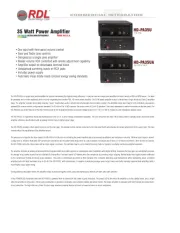
Congratulations on your selection of an RDL HD-Series Ultra-High-Efficiency commercial mixer amplifier. The HD-RA35UA is part of the world’s first full-featured environmentally conscious
“green” mixer amplifier series for commercial installations. This product includes studio quality microphone input stages, line-level transformer isolation, equalization, remote control capability
and integral analog compression coupled to sonically pleasing analog-filtered high efficiency Class D output stages. An internal low-power-consumption processor monitors usage demands
to completely shut down internal circuitry for maximum power conservation and extremely low long-term operating cost. The HD-Series mixer amplifiers are designed and manufactured in the
U.S.A. using the most advanced automated manufacturing and testing processes for years of reliable high performance and cost savings.
HD-RA35UA 25/70/100 V
OUTPUT CONNECTIONS MUST BE MADE BY
PERSONS ADVISED OR SUPERVISED TO
AVOID DANGERS AND PREVENT RISKS
WHICH ELECTRICITY MAY CREATE.
USE ONLY THE TERMINAL BLOCK
SUPPLIED WITH THE MODULE.
USE ONLY THE POWER SUPPLY
SUPPLIED WITH THE MODULE.
Produkspesifikasjoner
| Merke: | RDL |
| Kategori: | miksestav |
| Modell: | HD-RA35UA |
Trenger du hjelp?
Hvis du trenger hjelp med RDL HD-RA35UA still et spørsmål nedenfor, og andre brukere vil svare deg
miksestav RDL Manualer

6 Oktober 2025

6 Oktober 2025
5 Oktober 2025
5 Oktober 2025
5 Oktober 2025
5 Oktober 2025

5 Oktober 2025
5 Oktober 2025
5 Oktober 2025
miksestav Manualer
- Chefman
- Clatronic
- Taurus
- Ideal
- Behringer
- G3 Ferrari
- Jata
- ECG
- Soundcraft
- Waring Commercial
- Morphy Richards
- Vox
- Esperanza
- Hanseatic
- Essentiel B
Nyeste miksestav Manualer
19 Oktober 2025
13 Oktober 2025

13 Oktober 2025

12 Oktober 2025

8 Oktober 2025

8 Oktober 2025

7 Oktober 2025

7 Oktober 2025

7 Oktober 2025

6 Oktober 2025