Reelcraft F7925 OLP Bruksanvisning

Reelcraft Hageslange F7925 OLP

Les nedenfor 📖 manual på norsk for Reelcraft F7925 OLP (12 sider) i kategorien Hageslange. Denne guiden var nyttig for 2 personer og ble vurdert med 4.5 stjerner i gjennomsnitt av 2 brukere

Side 1/12
Operating Instructions
Reelcraft Industries, Inc. • 2842 E Business Hwy 30, Columbia City, IN 46725
Ph: 800-444-3134 / 260-248-8188 • Fax: 800-444-4587 / 260-248-2605
Customer Service: 855-634-9109 • reelcraft@reelcraft.com • www.reelcraft.com
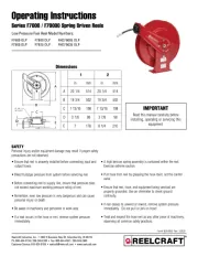
Series F7000 / F70000 Spring Driven Reels
Low Pressure Fuel Reel Model Numbers:
Ensure that reel is properly installed before connecting input and
output hoses.
Bleed fluid/gas pressure from system before servicing reel.
Before connecting reel to supply line, ensure that pressure does
not exceed maximum working pressure rating of reel.
Remember, even low pressure is very dangerous and can cause
personal injury or death.
Be aware of machinery and personnel in work area.
If a leak occurs in the hose or reel, remove system pressure
immediately.
A high tension spring assembly is contained within the reel.
Exercise extreme caution.
Pull hose from reel by grasping the hose itself, not the control
valve.
Ensure that reel, hose, and equipment being serviced are
properly grounded. Use an ohmmeter to check ground
continuity.
If reel ceases to unwind or rewind, remove system pressure
immediately. Do not pull or jerk on hose!
Treat and respect the hose reel as any other piece of machinery,
observing all common safety practices.
SAFETY
Personal injury and/or equipment damage may result if proper safety
precautions are not observed.
Form# 829-696E Rev: 1/2020
F7600 OLP F7800 OLP FHD79005 OLP
F7900 OLP F7925 OLP FHD79035 OLP
Read this manual carefully before
installing, operating or servicing this
equipment.
IMPORTANT
Dimensions
1 2
in mm in mm
A 20 1/4 514 20 1/4 514
B 19 3/4 502 19 3/4 502
C 7 13/16 198 7 13/16 198
D 3 7/8 98 3 7/8 98
E 7 178 8 1/4 210
D
Series F7000 / F70000 Spring Driven Hose Reels
Page 2
www.reelcraft.com
INSTALLATION INSTRUCTIONS
MOUNTING
Caution: Unless reel was specified
differently when ordering, maximum
installation height is 16 feet. Do not
exceed this distance.
1. Unpack and inspect reel for damage.
Turn by hand to check for smooth
operation. Check for completeness.
2. Configure reel for top, side or
bottom-wind hose dispensing by
removing nuts (1) securing guide arm
bracket (2). Position guide arm bracket
to desired location, and replace nuts.
Caution: When changing guide arm
positions, the U-bolt must be placed in
the proper location as instructed in
figure A below. The reel can
“latch out” during use if this
instruction is not adhered to.
3. Position reel on floor, wall, or ceiling.
Secure into place using four (customer
supplied) bolts (3).
INSTALLING THE INPUT HOSE(S)
Warning: Ensure that supply line
pressure does not exceed maximum
working pressure rating of reel. Apply
pipe thread sealant to all threads.
Caution: Use flexible hose connection at
input. Do not use rigid plumbing.
1. Connect supply line hose (4) to main
shaft input (5) as indicated in
illustration.
INSTALLING THE OUTPUT HOSE(S)
Warning: Use extreme caution; reel
under tension. Avoid releasing latch
mechanism. Apply pipe thread sealant to
all threads.
1. Manually turn sheave (10) until spring
is tight, back off 3 turns, then latch.
2. Route output hose(s) (11) through
guide arm bracket (2), U-bolts (12),
then through cutout (13) in spool as
indicated in illustration.
3. Connect output hose(s) (11) to swivel
(14) as indicated in illustration.
4. Tighten U-bolts (12).
5. Charge hose(s). Momentarily open
control valve to purge hose(s) of gases.
When fluid appears at control valve,
close valve. With hose(s) fully charged,
release latch and wind output hose(s)
onto reel.
ADJUSTMENTS
Warning: Use extreme caution; reel
under tension. Avoid releasing latch
mechanism. If necessary, adjust spring
tension on reel by adding or removing
wraps of hose from spool, one wrap at a
time, until desired tension is obtained.
Add wraps to increase tension. Remove
wraps to decrease tension.
SERVICE INSTRUCTIONS
User servicing of the reel is limited to
replacing input/output hoses only. Refer
all other repairs to an authorized service
person or directly to Reelcraft. Failure to
do so can result in personal injury and/or
equipment damage and may void the
warranty. Warning: Rewind hose on
reel, then bleed pressure from system
before performing the following proce-
dures.
1. Replace hoses in accordance with
procedures given in “Installation
Instructions” section of this manual.
Caution: When replacing drive spring,
hold the center of the spring down as the
hub is pulled out. If the center is allowed
to raise up, the spring may escape from
it’s container with enough force to cause
injuries.
When disposing of old or broken spring
assemblies, the coils should be welded or
wired together to prevent possible injury
to scrap handling personnel.
2. All mating moving parts are to be
lubricated with Perma Bond or Loctite
anti-seize compound.











Figure A
Series F7000 / F70000 Spring Driven Hose Reels
www.reelcraft.com
Page 3
Item
#
Description
#
Req.
F7600 OLP F7800 OLP F7900 OLP F7925 OLP
1 Swivel Assembly 1 S600923-2 S600923-2 602761-2 602761-2
3 90° Ell 1 None None S157-4 S157-4
4 Sheave Assembly 1 S260011 S260011 S260011 S260011
5 Drive Spring Assembly 1 S260028 S260037 S600023 S600023
6 Spring Arbor Assembly 1 S600621 S600621 S600621 S600621
7 Gasket 1 S260069 S260069 S260069 S260069
8 Spring Case Assembly 1 S260074 S260074 S260074 S260074
10 Main Shaft 1 S260095 S260095 260095-1 260095-1
11 1 1/4” Snap Ring 1 300007 300007 300007 300007
12 Base Assembly 1 S600016 S600016 S600016 S600016
13 1/2-13 Set Screw 1 S35-84 S35-84 S35-84 S35-84
14 Guide arm with Rollers 1 S600017 S600017 S600017 S600017
15 Bumper Stop Assembly 1 None None None 3-HR1004-3
16 5/16-18 Locknut 4 300107 300107 300107 300107
17 10-32 x 3/8” Nyloc Nut 7 S82-15 S82-15 S82-15 S82-15
18 1/2-20 x 5/8” Hex Nut 1 S280-8 S280-8 S280-8 S280-8
19 Latch Spring 1 S260067 S260067 S260067 S260067
21 10-32 Shoulder Screw 1 S393-2 S393-2 S393-2 S393-2
22 Latch Pawl Assembly 1 S600018 S600018 S600018 S600018
23 3/8-24 Jam Nut 1 S76-106 S76-106 S76-106 S76-106
24 Spring Case Stud 1 S260031 S260031 S260031 S260031
25 U-bolt 1 3-117440 3-117440 5-117440 5-117440
26 1/4-20 x 3/8” Locknut Noted 261650-1 (2) 261650-1 (2) 300070 (4) 300070 (4)
28 Swivel Union 1 S257-26 S257-26 None None
Hose Assembly None None None 600160-1
Hose I.D. x Length None None None 3/4” x 25’
Reel Inlet Connection 1/2” FPT 1/2” FPT 3/4” FPT 3/4” FPT
Max. Operating Pressure 500 PSI 500 PSI 500 PSI 50 PSI
Max. Operating Temperature 210 °F 210 °F 210 °F 150 °F

Produkspesifikasjoner

Merke: Reelcraft
Kategori: Hageslange
Modell: F7925 OLP

Trenger du hjelp?

Hvis du trenger hjelp med Reelcraft F7925 OLP still et spørsmål nedenfor, og andre brukere vil svare deg