Toa VX-3008F Bruksanvisning

Les nedenfor 📖 manual på norsk for Toa VX-3008F (130 sider) i kategorien Ikke kategorisert. Denne guiden var nyttig for 3 personer og ble vurdert med 4.5 stjerner i gjennomsnitt av 2 brukere

Side 1/130
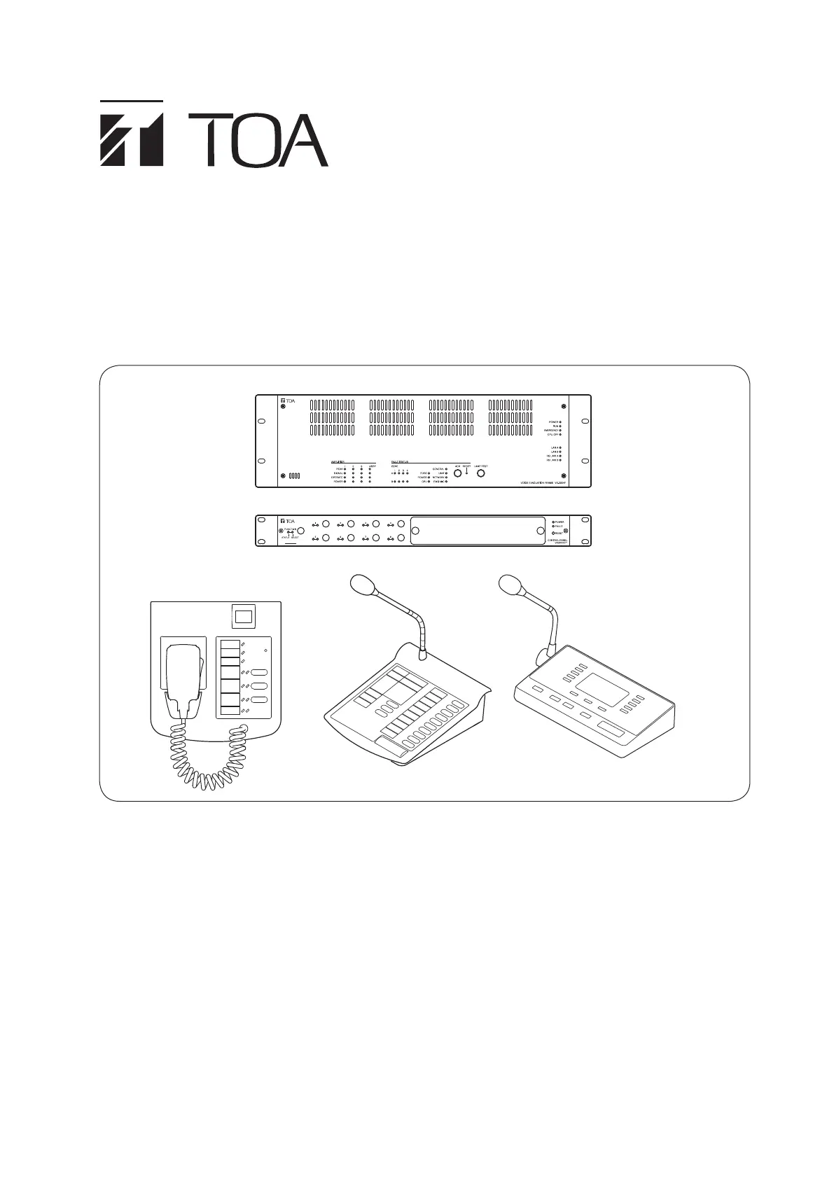
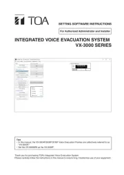
OPERATING INSTRUCTIONS
INTEGRATED VOICE EVACUATION SYSTEM
VX-3000 SERIES
RM-200SF
VX-3004F
VX-3000CT
RM-300X RM-500
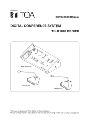
Thank you for purchasing TOA's Integrated Voice Evacuation System.
Please carefully follow the instructions in this manual to ensure long, trouble-free use of your equipment.
2
TABLE OF CONTENTS
Chapter 1 : NOMENCLATURE
1. VX-3004F, VX-3008F, AND VX-3016F
VOICE EVACUATION FRAME ............................................................... 1-2
2. RM-200SF FIREMAN’S MICROPHONE AND RM-320F
REMOTE MICROPHONE EXTENSION ........................................... 1-6
2.1. RM-200SF ......................................................................................................... 1-6
2.2. RM-320F ........................................................................................................... 1-8
3. RM-300X REMOTE MICROPHONE AND RM-210F
REMOTE MICROPHONE EXTENSION
........................................... 1-9
3.1. RM- 300X ........................................................................................................... 1-9
3.2. RM-210F ......................................................................................................... 1-10
4. RM-500 REMOTE MICROPHONE .................................................... 1-11
Chapter 2 : INDICATOR STATUS OF CONTROL PANEL AND
REMOTE MICROPHONES
1. VX-3000CT CONTROL PANEL ............................................................. 2-2
1.1. Indicator State at the Time of Input Volume Adjustment ................................... 2-2
1.2. Indicator State at the Time of Output Volume Adjustment ................................ 2-2
1.3. Indicator State at the Time of Zone Selection .................................................. 2-3
1.4. Indicator State at the Time of Base Pattern Change ........................................ 2-4
1.5. Indicator State at the Time of General-Purpose Broadcast Pattern ................. 2-4
1.6. Indicator State at the Time of General/BGM Broadcast ................................... 2-5
1.7. Indicator State at the Time of Intended Control Input ....................................... 2-6
1.8. Indicator State at the Time of Intended Control Output (Pulse) ........................ 2-7
1.9. Indicator State at the Time of Intended Control Output (Level) ......................... 2-7
1.10. Indicator State at the Time of Zone Volume Adjustment (Pulse) .................... 2-8
1.11. Indicator State at the Time of Input Volume Adjustment (Pulse) ..................... 2-9
1.12. Indicator State at the Time of Emergency Warning Broadcast ...................... 2-10
1.13. Indicator State at the Time of Sleep Mode Power On ................................... 2-11
2. RM-200SF FIREMAN’S MICROPHONE AND RM-320F
REMOTE MICROPHONE EXTENSION
......................................... 2-12
2.1. Indicator State at the Time of Zone Selection ................................................. 2-12
2.2. Talk Key Indicators .......................................................................................... 2-13
2.3. Indicator State at the Time of Base Pattern Change ...................................... 2-14
2.4. Indicator State at the Time of General-Purpose Broadcast Pattern ............... 2-14
2.5. Indicator State at the Time of General/BGM Broadcast ................................. 2-15
2.6. Indicator State at the Time of RM Broadcast Status Display .......................... 2-15
2.7. Indicator State at the Time of Lamp Test ......................................................... 2-16
2.8. Indicator State at the Time of Failure Output Receipt ..................................... 2-17
2.9. Indicator State at the Time of Failure Output Reset ........................................ 2-18
2.10. Indicator State at the Time of Emergency Broadcast Pattern Start .............. 2-19
2.11. Indicator State at the Time of Emergency Broadcast Pattern Stop ............... 2-20
2.12. Indicator State at the Time of Emergency Broadcast Pattern Start/Stop ...... 2-21

Produkspesifikasjoner

Merke: Toa
Kategori: Ikke kategorisert
Modell: VX-3008F
Vekt: 7900 g
Bredde: 482 mm
Dybde: 345 mm
Høyde: 132.6 mm
Inngangsspenning: 31 V
Produktfarge: Sort
Strømforbruk (vanlig bruk): 85 W
Driftstemperatur (T-T): -5 - 45 °C
Bærekraftsertifikater: CE
Signal-til-støy-forhold (SNR): 60 dB
Kroppsmateriale: Stål
Antall RJ45-porter: 12
Dekselfarge: Sort
Bærekraftsamsvar: Ja
Frekvensrekkevidde: 40 - 20000 Hz
Total harmonisk forvrengning pluss Noise (THD + N)(1 kHz): 1

Trenger du hjelp?

Hvis du trenger hjelp med Toa VX-3008F still et spørsmål nedenfor, og andre brukere vil svare deg