Tripp Lite PowerVerter PV700HF Bruksanvisning
Tripp Lite
batteri
PowerVerter PV700HF
Les nedenfor 📖 manual på norsk for Tripp Lite PowerVerter PV700HF (24 sider) i kategorien batteri. Denne guiden var nyttig for 17 personer og ble vurdert med 4.3 stjerner i gjennomsnitt av 9 brukere
Side 1/24

1
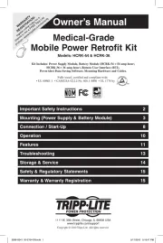
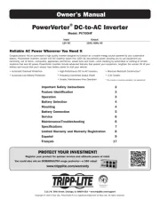
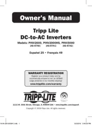
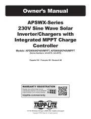
Owner’s Manual
Reliable AC Power Wherever You Need It
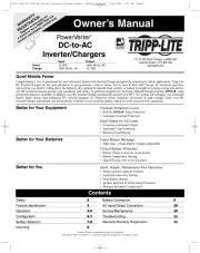
Congratulations! You've purchased a high-quality Inverter designed to function as a mobile energy source powered by your automotive
battery. PowerVerter Inverters convert 12V DC (battery) power into 120V AC (household) power, allowing you to use equipment you
commonly use at home—computers, appliances, electronics, power tools and more—while traveling by automobile or working at remote
locations that lack AC power. PowerVerter Inverters include advanced features that protect your equipment, lengthen the service life of your
battery and ensure that you'll always have battery power to start your vehicle:
PowerVerter
®
DC-to-AC Inverter
Model: PV700HF
Input Output
12V DC 120V, 60Hz AC
• Automatic Overload Protection
• Automatic Low Battery Protection
• High-Performance DC-to-AC Inversion
• Frequency-Controlled Output Power
• Simple, Maintenance-Free Operation
• Moisture-Resistant Construction*
• 3 AC Outlets
* The inverter is moisture-resistant, not waterproof.
1111 W. 35th Street, Chicago, IL 60609 USA • www.tripplite.com/support
Copyright © 2014 Tripp Lite. PowerVerter® is a registered trademark of Tripp Lite. All rights reserved.
Important Safety Instructions 2
Feature Identification 3
Operation 3
Battery Selection 4
Mounting 4
Battery Connection 5
Service 6
Maintenance/Troubleshooting 6
Specifications 7
Limited Warranty and Warranty Registration 8
Español 9
Français 17
Produkspesifikasjoner
| Merke: | Tripp Lite |
| Kategori: | batteri |
| Modell: | PowerVerter PV700HF |
Trenger du hjelp?
Hvis du trenger hjelp med Tripp Lite PowerVerter PV700HF still et spørsmål nedenfor, og andre brukere vil svare deg
batteri Tripp Lite Manualer
18 August 2025
18 August 2025
18 August 2025
18 August 2025
18 August 2025

18 August 2025
18 August 2025
18 August 2025
18 August 2025
18 August 2025
batteri Manualer
- Fluke
- Xtorm
- SmallRig
- DJI
- True Blue Power
- Growatt
- Uniden
- Sven
- Pawa
- SWIT
- Milwaukee
- Gude
- SOUNDBOKS
- EcoFlow
- Toolcraft
Nyeste batteri Manualer
13 Oktober 2025
30 September 2025
30 September 2025
29 September 2025

29 September 2025
27 September 2025
26 September 2025
14 September 2025