Tripp Lite PowerVerter RV1250ULHW Bruksanvisning
Tripp Lite
batteri
PowerVerter RV1250ULHW
Les nedenfor 📖 manual på norsk for Tripp Lite PowerVerter RV1250ULHW (12 sider) i kategorien batteri. Denne guiden var nyttig for 15 personer og ble vurdert med 4.4 stjerner i gjennomsnitt av 8 brukere
Side 1/12
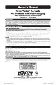
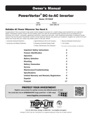
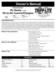
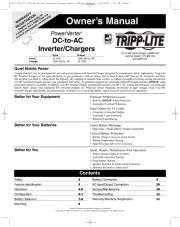
Owner’s Manual
Quiet Mobile Power
Congratulations! You’ve purchased the most advanced, feature-rich Inverter/Charger designed for recreational vehicle applications. Tripp Lite
RV Inverter/Chargers are the quiet alternative to gas generators—with no fumes, fuel or noise to deal with! You get AC electricity anywhere
and anytime you need it: rolling down the highway, dry camping in majestic back country or parked overnight at a money-saving non-electric
site. RV Inverter/Chargers provide your equipment with utility- or generator-supplied AC electricity (filtered through premium ISOBAR
®
surge
protection) whenever available. In addition, your RV Inverter/Charger automatically powers your RV’s 12V system and recharges your connected
battery bank—doing what traditional RV converter/chargers do. Whenever power blackouts, brownouts or high voltages occur, your RV
Inverter/Charger immediately and automatically switches over to inverting battery output to power connected AC equipment.
Better for Your Equipment Premium Protection Levels
• Built-In ISOBAR
®
Surge Protection
• Automatic Overload Protection
Ideal Output for All Loads
• Frequency-Controlled Output
• Automatic Load Switching
• Balanced Load Sharing
Better for Your Batteries Faster Battery Recharge
• High-Amp, 3-Stage Battery Charger (adjustable)
Critical Battery Protection
• Battery Charge Conserver (Load Sense)
• Battery Temperature Sensing
• High-Efficiency DC-to-AC Inversion
Better for You Quiet, Simple, Maintenance-Free Operation
• Multi-Function Lights & Switches
• Automatic Generator Starting
• Dead Battery Startup
• Ignition Interlock & In/Out Swap Protection
• Moisture-Resistant Construction*
Safety 2
Feature Identification 3
Operation 4-5
Configuration 5-7
Battery Selection 7-8
Mounting 8
Battery Connection 9
AC Input/Output Connection 10
Service/Maintenance 10
Troubleshooting 11
Warranty/Warranty Registration 11
PowerVerter
®
DC-to-AC
Inverter/Chargers
Input Output
Invert: 12 VDC 120V, 60 Hz. AC
Charge: 120V, 60 Hz. AC 12 VDC
1111 W. 35th Street, Chicago, IL 60609 USA
Customer Support: (773) 869-1234
www.tripplite.com
* Inverter/Chargers are moisture-resistant, not waterproof.
Copyright © 2008. PowerVerter
®
is a registered trademark of Tripp Lite. All rights reserved.
Contents
WARRANTY
REGISTRATION
Register on-line today for
a chance to win a FREE Tripp Lite
product! www.tripplite.com/warranty
200712159 93-2768 RV Series Inverter-Charger Owner’s Manual_Eng.qxd 2/29/2008 1:55 PM Page 1
Produkspesifikasjoner
| Merke: | Tripp Lite |
| Kategori: | batteri |
| Modell: | PowerVerter RV1250ULHW |
Trenger du hjelp?
Hvis du trenger hjelp med Tripp Lite PowerVerter RV1250ULHW still et spørsmål nedenfor, og andre brukere vil svare deg
batteri Tripp Lite Manualer
18 August 2025
18 August 2025
18 August 2025
18 August 2025
18 August 2025

18 August 2025
18 August 2025
18 August 2025
18 August 2025
18 August 2025
batteri Manualer
- Sven
- Growatt
- Mestic
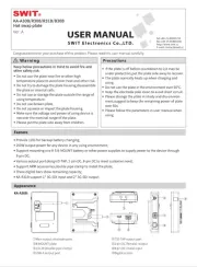
- SWIT
- DataVideo
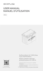
- EcoFlow
- Biltema
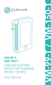
- Pawa
- Parkside
- SOUNDBOKS
- Milwaukee
- True Blue Power
- Belkin
- Uniden
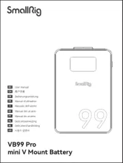
- SmallRig
Nyeste batteri Manualer
13 Oktober 2025
30 September 2025
30 September 2025
29 September 2025

29 September 2025
27 September 2025
26 September 2025
14 September 2025