Tripp Lite UT750UL Bruksanvisning
Tripp Lite
batteri
UT750UL
Les nedenfor 📖 manual på norsk for Tripp Lite UT750UL (12 sider) i kategorien batteri. Denne guiden var nyttig for 14 personer og ble vurdert med 4.8 stjerner i gjennomsnitt av 7.5 brukere
Side 1/12
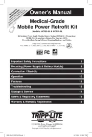
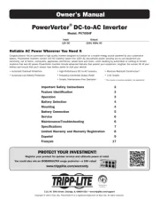
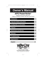
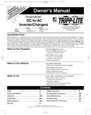
Owner’s Manual
Safety/Warranty/Warranty Registration 2
Feature Identification 3
Operation 3-4
Configuration 5-6
Battery Selection 7
Mounting 8
Battery Connection 9
AC Input/Output Connection 10
Service/Maintenance 11
Troubleshooting 11
Tripp Lite Utility/
Work Truck DC-to-AC Inverters
1111 W. 35th Street, Chicago, IL 60609 USA
Customer Support: (773) 869-1234
www.tripplite.com
* See "Utilize Automatic Generator Starter Capability" in the Configuration section for details. ** Depending on power needs, users may wish to complement a Tripp Lite Utility/Work Truck Inverter
with a larger vehicle alternator and one or more auxiliary batteries. *** Tripp Lite Utility/Work Truck Inverters are moisture-resistant, not waterproof. Copyright © 2006 Tripp Lite.
Contents
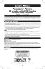
POWER BOOSTER!
Includes built-in charger for optional overnight recharging
of vehicle battery from shore power!
Quiet, Economical Mobile Power…
Congratulations! You've purchased one of the most advanced, feature-rich Inverters designed for utility/work truck applications. Tripp Lite Utility/Work Truck
Inverters provide quiet, convenient mobile power for every application: computers, TVs, electronic test equipment, power tools, pumps, compressors, blowers,
lights, power supplies, radios, cell phone chargers and more. Since Tripp Lite Inverters draw power directly from vehicle batteries, they are the quiet, economical
power alternative in residential environments or late-night job sites—without the noise, fumes, capital outlays, maintenance costs and occasional power overkill
of generators! For generator-equipped trucks, they provide crews with the option of silent power.*
…With Optional Power-Boosting Functionality
In today's cost-cutting climate, fleet managers must get the most out of every vehicle—keeping trucks in the field longer, operating an ever-growing array of
power tools. Standard vehicle alternators and batteries, however, often can't keep up with the increased power demand. When alternators recharge batteries at
a slower rate than they are discharged, that leaves a power deficit for the next day's jobs and dramatically shortens battery service life. Tripp Lite Utility/Work
Truck Inverters, with the addition of a built-in battery charger, help to overcome this power deficit. When optionally connected to shore power at the end of the
day, Tripp Lite Utility/Work Truck Inverters quickly and safely recharge vehicle batteries, ensuring that maximum power is available for the next day's service
schedule.** In addition, Tripp Lite Utility/Work Truck Inverters out-muscle other inverters on the market with peak power—handling tough loads like motors,
compressors and incandescent lamps with ease.
Rugged Reliability Stands Up to Demanding Service Fleet Applications
• Powers everything from lights and power tools to sensitive testing equipment with frequency-controlled output
• Operates under the most severe conditions with heavy-duty, weather-resistant construction which meets tough marine standards for shock, vibration and
moisture resistance***
• Enhances crew safety in moist environments with dual GFCI outlets (on select models)
• Delivers more AC power from your truck's system with high-efficiency DC-to-AC inversion
• Saves precious vehicle space with compact cabinet size
Battery Charger (Built-In) Provides Optional Overnight Charging
• Boosts battery to full charge for next day's jobs (on a routine or "as-needed" basis)
• Extends battery service life with safe, 3-stage charging and battery temperature-sensing function (featured on select models)
Remote Module (Included) Enables Convenient Control and Monitoring From Vehicle Cab
• Monitor battery voltage level and Inverter operating status
• Activate or deactivate Inverter with ease
WARRANTY
REGISTRATION:
register online today for a
chance to win a FREE Tripp Lite
product—www.tripplite.com/warranty
Produkspesifikasjoner
| Merke: | Tripp Lite |
| Kategori: | batteri |
| Modell: | UT750UL |
| Vekt: | 7890 g |
| Bredde: | 222.2 mm |
| Dybde: | 228.6 mm |
| Høyde: | 177.8 mm |
| Støynivå: | - dB |
| Opprinnelsesland: | China |
| Pakkevekt: | 9160 g |
| Sertifisering: | UL 458, CSA |
| Toppeffekt: | 1500 W |
| AC-inngangsspenning: | 120 V |
| AC-inngangsfrekvens: | 60 Hz |
| Produktfarge: | Sølv |
| Pakkedybde: | 271.8 mm |
| Pakkehøyde: | 320 mm |
| Pakkebredde: | 271.8 mm |
| Harmonisert system (HS)-kode: | 8504.40.9570 |
| Strømbeskyttelsesfunksjoner: | Over power, Overload |
| Viftediameter: | - mm |
| Total strøm: | 750 W |
| Masterkassens (ytterkassens) bruttovekt: | 9160 g |
| Masterkassens (ytterkassens) lengde: | 271.8 mm |
| Produkter per masterkasse (ytterkasse): | 1 stykker |
| Masterkassens (ytterkassens) bredde: | 271.8 mm |
| Masterkassens (ytterkassens) høyde: | 320 mm |
Trenger du hjelp?
Hvis du trenger hjelp med Tripp Lite UT750UL still et spørsmål nedenfor, og andre brukere vil svare deg
batteri Tripp Lite Manualer
18 August 2025
18 August 2025
18 August 2025
18 August 2025
18 August 2025

18 August 2025
18 August 2025
18 August 2025
18 August 2025
18 August 2025
batteri Manualer
- Pawa
- SOUNDBOKS
- Milwaukee
- Biltema
- DJI
- Growatt
- SmallRig
- Fluke
- SWIT
- Belkin
- Toa
- Parkside
- Kress
- Sven
- Gude
Nyeste batteri Manualer
13 Oktober 2025
30 September 2025
30 September 2025
29 September 2025

29 September 2025
27 September 2025
26 September 2025
14 September 2025