Valcom V-DCPI Bruksanvisning
Les nedenfor 📖 manual på norsk for Valcom V-DCPI (3 sider) i kategorien Klokke. Denne guiden var nyttig for 16 personer og ble vurdert med 4.7 stjerner i gjennomsnitt av 8.5 brukere
Side 1/3
Issue 3
1 947972
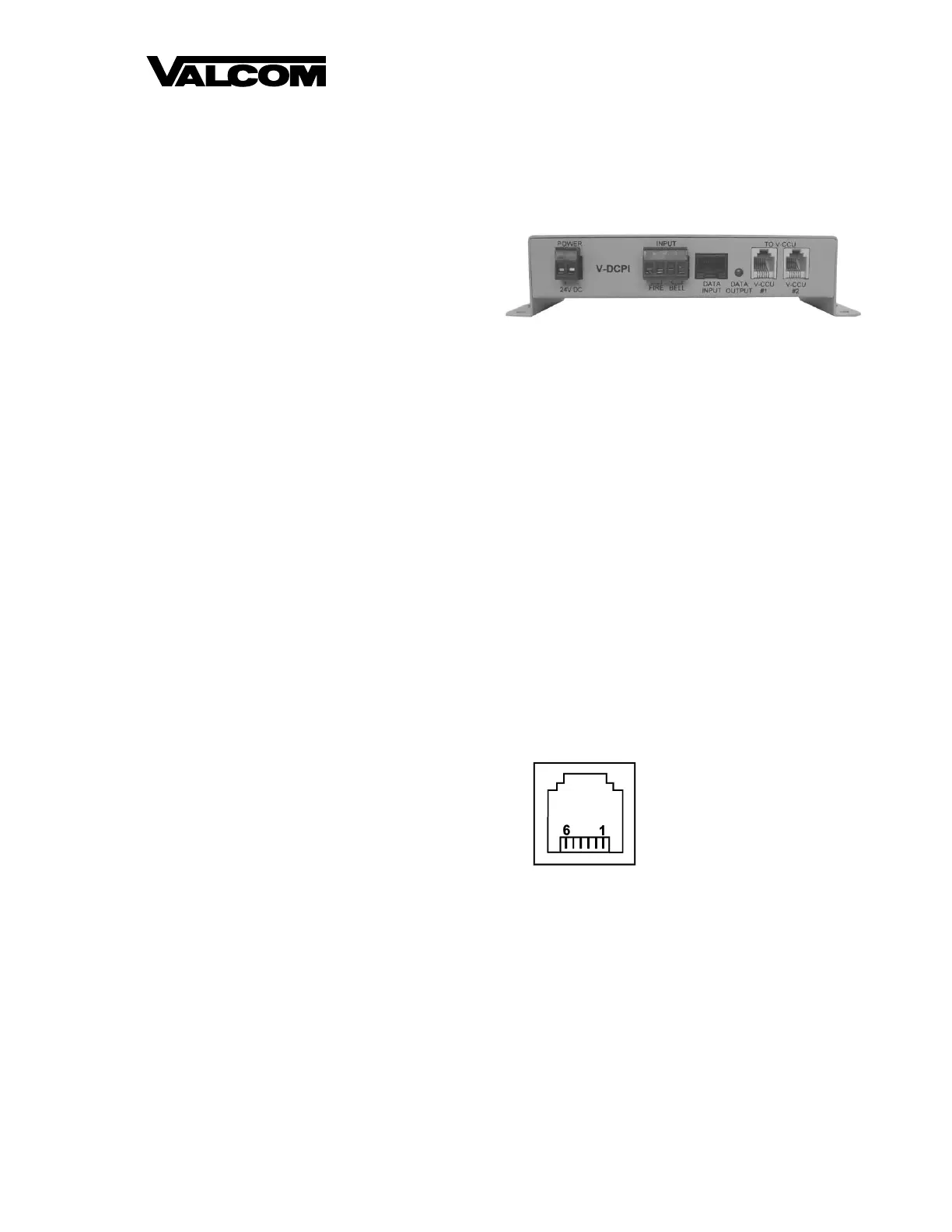
V-DCPI
Digital Protocol Interface
GENERAL
The Valcom Digital Protocol Interface conditions the
24-hour enhanced digital output from the Valcom
V-SER or V-2927 clock cards to allow the Valcom
communications systems using these cards to
provide clock correction data to a V-WMCA
Wireless Master Clock Transceiver, a V-WMCRA
Wireless Master Clock Repeater, or a V-CCU
2-Wire Clock Controller. The V-CCU is part of the
V-VCU package, which includes the V-CCU and a
power supply.
PACKAGE INCLUDES
1 Valcom V-DCPI Digital Protocol Interface
1 6-Pin Silver-Satin Cord
1 6-Pin RJ-11 Wiring Block
1 DB15 to RJ-45 Gender Changer
1 Ethernet Cable
SPECIFICATIONS
Output
Two individual RJ-11 data outputs
Inputs
RJ-45 for 24-hour enhanced digital from the
Valcom V-SER or V-2927 clock cards
-24VDC input power (for use when providing
data to V-WMCA or V-WMCRA only)
Dry contact closure input to display “Fire” or
“Bell” on wired digital display clocks that are
receiving data once a second.
Features
Data output LED indicator
Easy Connectivity
Dimensions/Weight
2.75”H x 7.70”W x 1.55”D
(6.98cm H x 19.55cm W x 3.94cm D)
1.5 lb. (0.68 kg)
Power Requirements
The V-DCPI requires -24VDC 50mA (1 VPU). The
unit may be powered by a V-CCU connection to the
V-CCU #1 RJ-11 or by connecting a suitable power
supply to the -24VDC input.
Environmental
Operating Temperature: -0 to +40° C
Humidity: 0-95% non-precipitating
Wiring Requirements
24AWG UTP, CAT 3/5/5E/6
Ethernet Cable
6-Pin Silver Satin Cord
6-Pin RJ-11 Wiring Block (for V-WMCA or
V-WMCRA connectivity). When used with a
V-WMCRA, the Wireless Master Clock
Repeater must be set to transmit mode.
INSTALLATION
Precautions
Failure to observe the following precautions could
result in damage to the V-DCPI:
Make all connections to the V-DCPI and
associated equipment with the input power
removed. Check and verify all connections
before applying power.
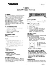
FIGURE 1: V-CCU RJ-11 DETAIL
Data is connected to the V-CCU, V-WMCA or
V-WMCRA via the two center pins of the “DATA
OUT” RJ-11 connector. Electrical shorting of any
RJ-11 pins or terminations may result in unit failure.
The 24V and GND connections are provided as a
power source for the V-DCPI Digital Protocol
Interface when used with a V-CCU 2-Wire Clock
Controller.
OPERATION
The green data output indicator will flicker when
correction data is supplied to the V-CCU outputs.
Pin 1 24V in from V-CCU
Pin 2 GND in from V-CCU
Pin 3 Data
Pin 4 Data
Pin 5 GND in from V-CCU
Pin 6 24V in from V-CCU
Produkspesifikasjoner
| Merke: | Valcom |
| Kategori: | Klokke |
| Modell: | V-DCPI |
Trenger du hjelp?
Hvis du trenger hjelp med Valcom V-DCPI still et spørsmål nedenfor, og andre brukere vil svare deg
Klokke Valcom Manualer
19 September 2025
18 September 2025
17 September 2025

15 Oktober 2024

15 Oktober 2024

15 Oktober 2024

15 Oktober 2024
Klokke Manualer
- Freek Vonk
- Mitsubishi
- Nedis
- Oregon Scientific
- Diesel
- Fossil
- Uniden
- Ferrari
- AMS
- Perel
- TFA
- Hama
- Adidas
- La Crosse Technology
- Breitling
Nyeste Klokke Manualer

6 Oktober 2025
1 Oktober 2025
26 September 2025
22 September 2025

22 September 2025

11 September 2025

10 September 2025
10 September 2025

10 September 2025
10 September 2025