Vestil UNI-4048-2-BLU-115-1 Bruksanvisning

Vestil Ikke kategorisert UNI-4048-2-BLU-115-1

Les nedenfor 📖 manual på norsk for Vestil UNI-4048-2-BLU-115-1 (14 sider) i kategorien Ikke kategorisert. Denne guiden var nyttig for 2 personer og ble vurdert med 4.5 stjerner i gjennomsnitt av 2 brukere

Side 1/14
02/05 03-126-121.doc
VESTIL MFG. CO. 1
VESTIL MANUFACTURING CORP.
2999 N. Wayne St., Angola, IN 46703
Ph: 260-665-7586 · Fax: 260-665-1339
E-mail: sales@vestil.com Website: www.vestil.com
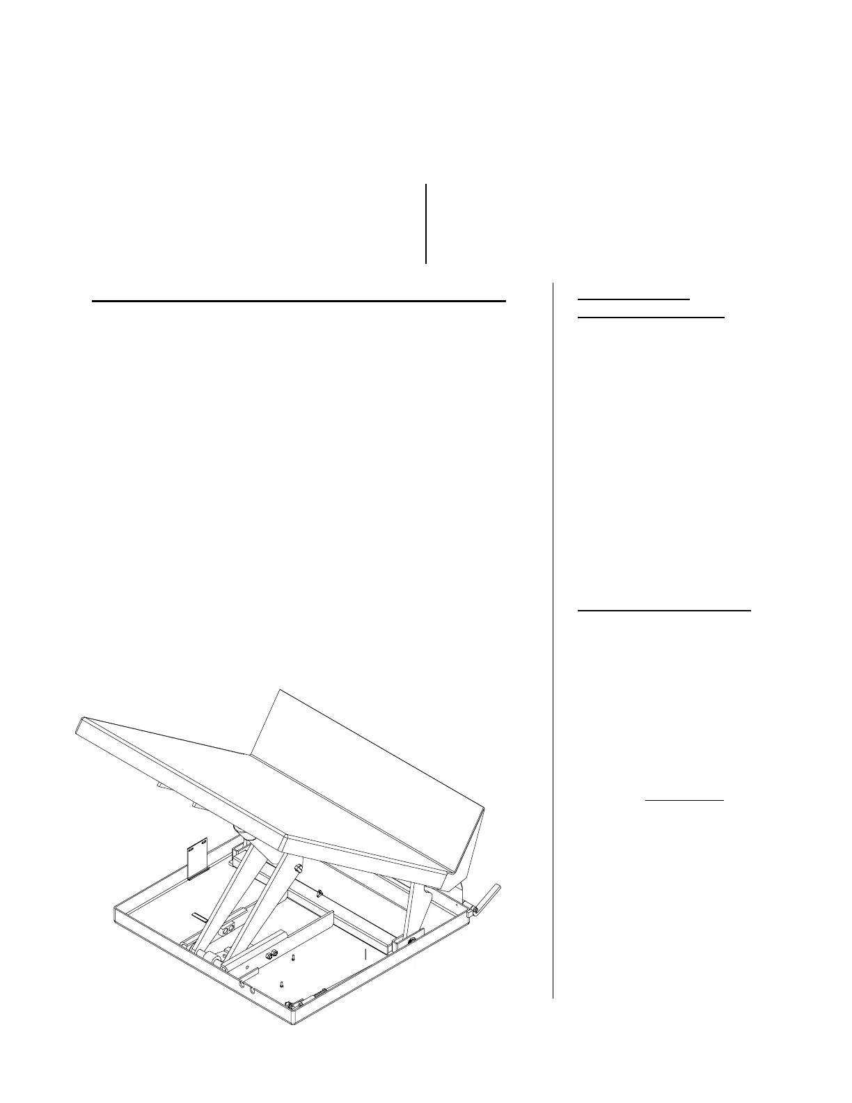
MODEL UNI
Serial number ____________
Installation Instructions ……………….....................… 2
Operation Instructions ……………………….……… 3-4
Routine Maintenance & Safety Checks ……………… 5
Exploded Structural Parts Drawing & BOM ………... 6-7
Motor and Transformer Connections ............................ 8
Electrical & Hydraulic Diagrams & BOM ………….. 9-10
Power Unit’s Operation ………………...…..………... 11
Troubleshooting …………………………....………… 12
Safety Label Identification .............................................13
Warranty …………………………………….……..…. 14
IMPORTANT NOTES, WARNINGS AND SAFETY INSTRUCTIONS
Ensure that all employees understand and follow the following.
o Read and understand the owner’s manual before using or servicing
the Uni-Tilt.
o The load must be removed and the platform supported or fully
lowered before any work is performed on the lift.
o Ensure that all safety and warning labels stay in place and are
legible.
o Do not use the Uni-Tilt if any damage or unusual noise is observed.
o Always watch the platform and the container carefully when the
tilter is in operation.
o Do not transport the Uni-Tilt with any load on the platform.
o Do not use brake fluid or jack oils in the hydraulic system. If oil is
needed, use an anti-wear hydraulic oil with a viscosity grade of
150 SUS at 100°F, (ISO 32 cSt @ 40°C), or Dexron transmission fluid.
o Contact the manufacturer for any needed MSDS information.
Do not perform any modifications to the Uni-Tilt without the
manufacturer’s approval. Failure to receive authorization for
changes to the equipment could void the warranty.
Maintenance and repairs are to be done only by personnel qualified
to perform the required work. Warranty labor charges will not
receive consideration without prior written authorization by the
manufacturer.
WHEN ORDERING
REPLACEMENT PARTS:
We take pride in using quality
parts on the equipment we
manufacture. We are not
responsible for equipment
problems resulting from the use
of unapproved replacement
parts.
To order replacement or
spare parts for this equipment,
contact the factory.
In any communication with
the factory please be prepared
to provide the machine’s serial
number, which is indicated on
the machine dataplate.
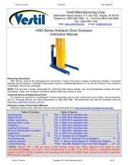
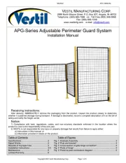
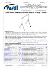
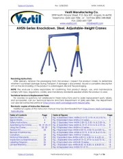
RECEIVING INSTRUCTIONS
Every unit is thoroughly
tested and inspected prior to
shipment. However, it is
possible that the unit could
incur damage during transit.
Inspect the unit closely when
it arrives. If you see evidence
of damage or rough handling to
either the packaging or to the
product when it is being
unloaded, immediately
make a
note of it on the Bill Of Lading!
It is important that you
remove the product’s packaging
upon its arrival to ensure that
there is no concealed damage
or to enable a timely claim with
the carrier for freight damage.
Also verify that the product
and its specifications are as
ordered.
O
WNER
S
MANUAL
02/05 03-126-121.doc
VESTIL MFG. CO. 2
INSTALLATION INSTRUCTIONS UNI
Review this entire page before installing the Uni-Tilt.
Consult the factory in the event there are any questions or problems at the time of installation, or for
information regarding optional features not covered by the owner’s manual.
Modifications or additions to the Uni-Tilt without prior manufacturer’s authorization may void the unit’s warranty.
The addition of ancillary equipment to the platform may necessitate that its load capacity be reduced.
The installation must be made so that it complies with all the regulations applicable to the machine and its
location. The end-user must verify that the supplied equipment is installed so it will be suited to the environment
in which it will be used.
Installation must be performed by suitably trained personnel with access to the appropriate equipment. The
electrical aspects of the installation should be performed by an electrician.
---------------------------------------------------------------------------------------
For a typical installation you will need the following:
1. A fork truck or hoisting means to unload the Uni-Tilt from the freight truck and set it into place.
2. A smooth, level, and adequately strong concrete surface on which to mount and operate the Uni-Tilt.
3. Concrete anchors, a masonry drill, a masonry bit, hand tools, grout, and steel shims. Consult the building’s
architect or facility engineer to determine the best size and type of hardware with which to anchor the machine to
the floor.
Portable units do not need to be anchored to the floor.
4. A power supply circuit and electrical disconnect matching the motor voltage and current requirements. Refer to
the machine’s dataplate, to the labels on the control enclosure, and to the electrical section in this manual for
more information. The end-user is responsible for supplying the branch circuit’s required ground fault and short-
circuit protection. (Motor overload protection is provided by a thermostat built into the motor.)
---------------------------------------
1. Move the tilter into place with a fork truck having at least a 2,000 lb capacity.
2. Temporarily connect the power supply to the pigtail cord supplied with the Uni-tilt, and raise the platform so the
unit’s safety maintenance prop(s) can be utilized. Lower the platform so the unit is supported by the prop(s).
o The maintenance prop(s) is located in the Uni-tilt’s frame next to the lifting assembly. It is a rod with a 90° bend.
To install the prop(s), raise the platform to its full raised height and insert the longer end through the holes in the
frame roller weldment. Lower the frame roller assembly unit it rests on the prop.
o If the platform must be raised without first having the proper power supply connected, raise the platform at the
side of the table opposite the platform cradle. Use rigging or insert a lift truck’s forks under the front edge of the
platform to tilt the platform up. Hold the frame down at the ends of the shipping 4 x 4’s on the hinged side of the
Uni-tilt while the platform is raised.
3. Anchor the frame to the floor through the holes located at the frame’s corners. (Non-portable units only.)
4. Make permanent connection to the power supply, using an appropriate wiring method.
5. Operate the Uni-Tilt through several full raise and lower cycles. Verify that the upper travel limit switch functions
properly.
6.
Check the hydraulic oil level. It should be filled to within 1” to 1½” of the reservoir’s fill hole. If oil is needed,
use an anti-wear hydraulic oil with a viscosity grade of 150 SUS at 100°F (ISO 32 at 40°C) or a non-synthetic
automatic transmission fluid.
7. Clean up any debris or spilled oil, and verify that all of the warning and safety labels are intact.
02/05 03-126-121.doc
VESTIL MFG. CO. 3
OPERATION INSTRUCTIONS UNI
o Consult ANSI MH29.2 - 2000, Safety Requirements for Industrial Tilters, Section 12, for the owner’s / user’s
responsibilities regarding the operation, care, and maintenance of this machine.
o Ensure that all employees involved in the operation of this machine understand and follow these instructions!
The standard model UNI (stationary) and UNI-P (portable) is suitable for use indoors in most industrial locations and
many commercial locations. It is intended to be used to lift and tilt stable, non-hazardous loads and containers having
a size or footprint approximately the same size as the platform.
Loading:
The load rating, in pounds, is shown on the machine dataplate located on the right front corner of the loading
(opposite the backstop) side of the platform . It indicates the net capacity of the machine, with a static load that is
centered and evenly distributed on the platform and having a vertical center of gravity not more than 20” above the
platform surface.
For applications involving side loading or loads with higher centers of gravity, consult the manufacturer.
The standard design Uni-Tilt is intended to be loaded with a fork truck or similar material handling equipment.
Always center the load, and place it up against the back cradle of the platform to prevent sudden load shifting when
the platform is tilted.
Do not exceed a rate of two feet per second when moving loads onto the platform.
Note: The addition of any ancillary equipment to the platform by third parties must be taken into account when
determining the maximum working load to be placed on the platform.
Warning: Do not exceed the Uni-tilt’s load ratings. Injury to personnel or permanent damage to the structure could
result from exceeding the listed capacity.
Operation:
Warning: Keep all personnel clear of the machine when it is in operation. Be certain no part of any person or object is
under any part of the platform before lowering the unit.
Caution: Always carefully watch the container and any load in it when it is in operation.
To raise or tilt the platform back toward the operator, press the “UP” pushbutton.
To lower or tilt the platform toward the floor, press the “DN” pushbutton.
When a pushbutton is not being pressed, the unit will hold its position wherever it is in its travel range.
The Uni-tilt can be operated in either one of two movement sequences.
Sequence #1:
Starting with the platform in the fully lowered position, press and hold the “UP” pushbutton while you push the
sequence selector pedal in against the frame of the table with your foot. After about five seconds, the pedal can
be released.
The platform will tilt back toward the operator until it reaches a tilt angle of 40° to the floor. It then will lift
vertically until the bottom of the cradle reaches a height of 16½” above the floor.
To lower the platform, press and hold the “DN” pushbutton. The platform will drop vertically until the bottom of
the cradle is about 12” above the floor, and then the platform will tilt down away from the operator until it is
again fully collapsed and level with the floor.
Sequence #2:
Again starting with the platform in the fully lowered position, press and hold the “UP” pushbutton. (Do not press
the sequence selector pedal.) The platform will rise and tilt back at the same time, until it reaches a height of 19”
from the floor to the bottom of the cradle and a tilt angle of 35°.
To return to the fully collapsed position, press and hold the “DN” pushbutton. The platform will both lower and
tilt down towards the floor concurrently until the unit is again fully collapsed and level with the floor.
On DC-powered units, attempting to raise the lift when the battery is low will cause the motor relay protection to
prevent the motor’s operation. Adequate battery voltage is indicated by a green LED on the motor relay. See the next
page for more notes regarding operation of battery-powered units.
Ensure that all safety and warning labels stay in place and are legible. Refer to the labels page in this manual.

Produkspesifikasjoner

Merke: Vestil
Kategori: Ikke kategorisert
Modell: UNI-4048-2-BLU-115-1

Trenger du hjelp?

Hvis du trenger hjelp med Vestil UNI-4048-2-BLU-115-1 still et spørsmål nedenfor, og andre brukere vil svare deg


Ikke kategorisert Vestil Manualer

Ikke kategorisert Manualer

Nyeste Ikke kategorisert Manualer